|
  

Wings, Ailerons, Flaps
In the QuickBuild kit, the
wings, ailerons, and flaps are delivered nearly complete structurally.
The remaining tasks associated with completing them and fitting them to
each other will be documented here.
Specifications:
| Wings: |
|
| Airfoil: |
NACA 23013.5 (i.e. NACA
23000-series with thickness 13.5% of chord length) |
| Planform: |
Rectangular (excluding
swept composite tip) |
| Twist, a.k.a washout: |
0° |
| Chord length: |
58.25 inch |
| Panel span, root to tip: |
109.5 inch (one wing
panel, excluding wing root fairing and composite wing tip) |
| Total span, tip to tip: |
300 inch (including
composite wing tips, fuselage, etc.) |
| Total wing area: |
121 ft² (total span ×
chord length) |
| Total aspect ratio: |
5.15 (total span / chord
length) |
| |
|
| Ailerons: |
|
| Type: |
Frise, with differential
deflection |
| Up deflection limit: |
+27° to +32° |
| Down deflection limit: |
-15° to -17° |
| |
|
| Flaps: |
|
| Type: |
Plain |
| Up deflection limit: |
0° |
| Down deflection limit: |
-40° |
Running Total Hours:
0.0
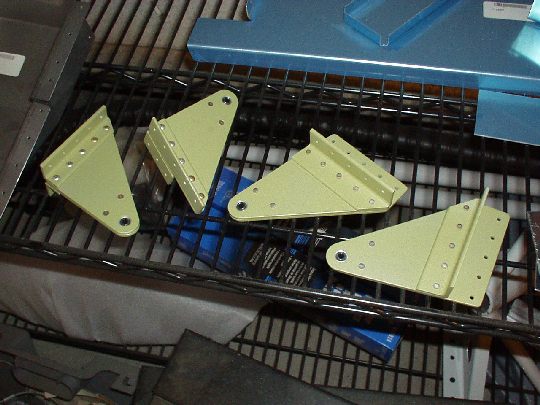
 | 2006.03.18:
(2.0) Started preparing
(edge-finishing, etc.) parts for the the aileron attach brackets. |
| 2006.03.19:
(1.5) Done edge finishing the
aileron attach brackets. |
| 2006.03.21:
(1.0) Applied corrosion
protection (AKZO) to the aileron attach bracket parts. |
| 2006.03.22:
(1.0) Riveted the aileron
attach brackets.
 |
| 2006.04.xx:
(2.0) Edge-finished the
aileron gap fairings. |
| 2006.04.10:
(1.0) Match-drilled the
aileron attach brackets to the wings. Had to do some more
trimming so that they would nest in the radius of the rear spar flange
and sit flat on the spar web. So... I have to wait until I can
touch up the primer in the trimmed area before installing them. |
| 2006.04.13:
(1.5) Started trimming and
edge finishing the flap braces. |
| 2006.04.19:
(1.0) Done trimming and
edge finishing the flap braces. |
| 2006.04.22:
(3.0) Sprayed AKZO on on the flap
braces, aileron gap fairings, inspection hole cover plates, and the
areas I had to trim on the aileron attach brackets. |
| 2006.04.23:
(1.0) Started installing the aileron
attach brackets to the wing. Got as far as I could reach with
the squeezer. |
| 2006.04.29:
(0.5) Finished riveting the aileron
attach brackets to the wing. Used the squeezer with a 4"
yoke and a 5/8" tall flat set, effectively creating a longeron
yoke with a 4" reach. I bought the 5/8" tall flat set
from Avery. |
| 2006.04.30:
(1.5) Match-drilled the A-406-1 and
A-407 brackets to the ailerons. |
| 2006.05.03:
(0.5) Tapped the tie-down blocks to
3/8-16 coarse thread for the Van's tie-down rings. |
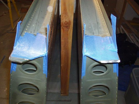
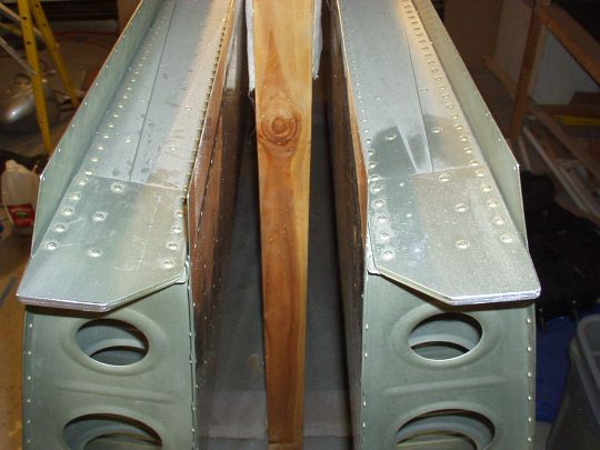
| 2009.05.28:
(0.0) Finally got back to the wings
a couple of weeks ago. Here's a summary:
Trimmed the inboard ends of the aft spars per DWG 38. Rough cuts
with a die grinder, just a little bit at a time to keep heat buildup
in check, then finish with a file. Some builders report an
interference between the inboard end of the aft spar and a domed rivet
just above the attach point on the fuselage, necessitating either
additional trimming of the spar or replacement of the rivet with a
flush head Cherry Max. I'm holding off on this for now.
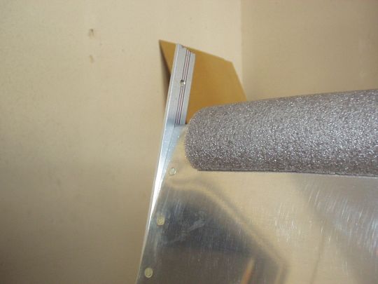
Installed the aileron gap fairings. An issue came up, where the
top skins needed to be bent downwards slightly into position.
Not a problem where the aileron gap fairing will hold them in place
with minimal tension. But there's a section of the outboard top
skin that extends inboard of the ailerons and is therefore not
supported by the aileron gap fairing, so it needed to be pre-bent by
hand so that it will match the contour of the supported area.
Did this carefully with good results. Also, the aileron gap
fairings needed to be trimmed slightly to clear some interference with
the aileron hinge brackets.
Fitted the ailerons to the wing. Installed the A-406 and 407
brackets to the ailerons, and mated them to the wings. DWG 13A
shows the spacers (washers and aluminum tubing) around the bearings
that set the spanwise position of the ailerons, noting that these
spacers may have to be adjusted for "proper fit".
Indeed, the spacers as called out didn't quite add up on my
wings/ailerons. I called up Van's to make sure I knew what
constrains this "proper fit", if there are any critical
dimensions. They assured me that this wasn't critical
aerodynamically, and that I just had to make sure that there is
adequate clearance, nominally 1/4", minimum 3/16", between
the aileron and the flap and between the aileron and the wing
tip. They suggested that I initially set my spacers for the
middle of the range of adjustment that I have, so that I can later
tweak it slightly in either direction to even out the clearances to
the flap and wingtip. Sounds good to me. So, using the
outboard bearing as reference, my range of adjustment is as
follows. Most inboard aileron position: three standard washers
outboard of the bearing, one standard washer inboard of the
bearing. Most outboard aileron position: two standard washers
outboard of the bearing, two standard washers inboard of the
bearing. Center and initial aileron position: two standard
washers and one thin washer outboard of the bearing, one standard
washer and one thin washer inboard of the bearing. Until I have
the flaps and wing tips fitted, I'll hold off on making the aluminum
spacers for the inboard aileron bearings. CORRECTION 2009.09.14:
The stackups of washers listed above are too wide. The aileron
bracket sits more squarely with one thin washer less. The two
possible stackups are therefore two standard washers outboard and one
standard plus one thin washer inboard, or two standard and one thin
outboard and one standard only inboard.
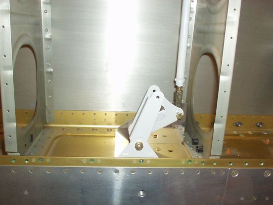
Rigged the ailerons to the bellcranks. Firstly, I noticed that
DWG 15A specified a dimension of 2-7/16" from the aft face of the
spar web to the center of the bolt on the bellcrank, while the actual
W-730 bellcrank jig used to set this dimention actually measured
2-3/8". Slight discrepancy, but I called Van's to clear
this up. They instructed me to use the W-730 jig and not worry
about the plans. Ok... Moving on, I made a simple jig to
set the neutral position of the ailerons themselves. The neutral
position is specified as the trailing edge of the aileron being
in-line with the two tooling holes in the aft wing rib. I used a
piece of Al angle and a couple of 3/16" AN bolts that slide
through it and into the tooling holes, and marked a line extending
through the centers of both bolts. Simple and effective.
One aileron at a time, I held the bellcrank in its neutral position
using the W-730 bellcrank jig, and adjusted the pushrod end bearings
until the aileron was also in its neutral position. Note that
these are the skinny pushrods from the bellcrank to the aileron.
The fat pushrods that go the fuselage haven't entered the equation
yet. Note also that I have not yet made the spacers for the
pushrod attachment to the aileron. I'll hold off on these until
the flaps and wing tips are fitted, and I've determined the final
span-wise position of the ailerons.
Now I'm starting fit the various sensors and actuators that will go in
the wing, so that I can finally close out the outboard bottom
skins. These will include the pitot
probe, AoA ports, OAT probes, autopilot
aileron servo, and landing lights. Wiring runs will also
have to be provided for the strobes, nav lights, and antennas that
will be installed in the wing tips. |
| 2009.09.09:
(0.0) Update on various tasks in
the wings:
I created some drawings (in OpenOffice Draw) to plan the layout of the
various sensors, actuators, wiring, and plumbing runs in the
wings. Also created a spreadsheet (in OpenOffice Calc) to select
appropriate wire gauges for the wiring runs. I'll put these up
on the web page soon.
Installation/fitting of the various sensors and actuators is coming
along nicely. These are documented in their respective pages.
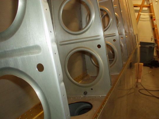
Holes for wiring
Started making accomodations for the physical wiring runs. I
considered several options, including those suggested by Van's in this
note. I ultimately decided to add a hole in the ribs as
shown in option 2, but use snap bushings rather than conduit [I don't
see that conduit would add much utility in this case, and it presents
potential problems with chafing as the wires enter/exit the
conduit]. My plan is to select snap bushings that are just
slightly bigger in diameter than the wiring harness at every point in
the wing. I don't have all the needed varieties of wire and
cable yet to get these measurements, but I can make some rough
guesses. On the inboard section of the wing (wing root to
aileron bellcrank) 1/2" diameter or less should suffice, and on
the outboard section of the wing (aileron bellcrank to wing tip)
3/8" diameter or less should suffice. I therefore drilled
the holes in the inboard section to 5/8", which can accomodate
snap bushings with inner diameters up to 0.500", and drilled the
holes in the outboard section to 1/2", which can accomodate snap
bushings with inner diameters up to 0.391". Snap bushings
with smaller inner diameters are also available for these outer
diameters. See chart
of available Heyco snap bushings.
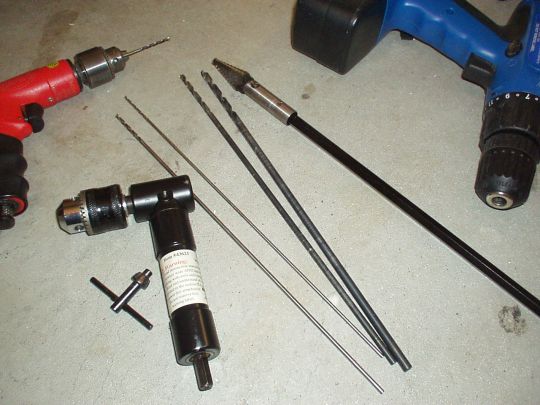
Drilling these holes is another instance of a task that could have
been performed very easily before the wing was assembled, but was a
lot more tricky on a pre-assembled QB wing, especially on the inboard
section where there are several closely spaced ribs and the bottom
skin is already on. I first used a properly scaled printout of
the drawing in
Van's note to locate and pilot-drill all the holes. It
ultimately took many steps, some yoga-like body contortions, an angle
drill adapter, drill extensions, standard drill bits, extra-long drill
bits, and unibits to enlarge the holes to their final size. What
finally made the job possible (and would have made it just a bit
simpler if I had it a couple of days sooner) was a 12" drill
extension for 3/8" shaft diameter bits (Irwin #3 unibit) that
could fit through a 5/8" hole. To my surprise I couldn't
find such a thing. But I did find one that had a 3/4" max
outer diameter, and my buddy Buzz was kind enough to have one his
buddies machine it down for me on a lathe to 9/16" outer
diameter. The original tool was a Ridgid 12" Hole Saw
Extension, p/n 7035. It was about $10 at the aerospace isle at
Home Depot. Note that Home Depot also had extensions for
1/4" shaft diameter with about 9/16" max outer diameter, and
perhaps this could have been bored out to 3/8" inner
diameter. Just another option.
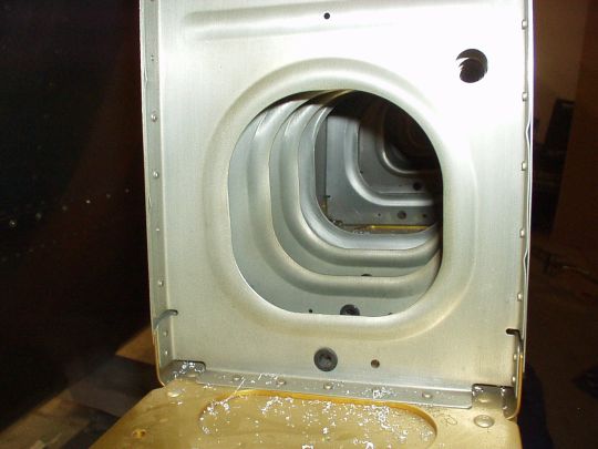
OUTBOARD BOTTOM SKINS:
Working toward getting the outboard bottom skins ready to close.
Firstly, I had a lot of work to do on the rib flanges. This is
yet another instance where doing the job right prior to wing
assembly would have been a lot easier. Unfortunately, the QB
factory did flute the rib flanges, but seemingly without any
particular objective in mind. The rib flanges were far from
square to the rib webs, and the rib webs (and more importantly the
flange rivet lines) were far from straight. I took several hours
to get these into shape.
Secondly, a few of the small rib flanges that meet the main and aft
spars are somewhat mis-shapen and create a gap between themselves and
the spar. In most cases the gap is sufficiently small that it
should pull together when riveted. But on the outboard rib of
the left wing, the gap to the rear spar is substantial. I made a
shim from 0.032" aluminum to fill the gap.
Now to the skins themselves. I decided to dress the edges and
prime the inside surfaces before match-drilling the holes. When
I removed the blue protective plastic from the left wing skin I had an
unpleasant surprise: the beginning of filliform corrosion was evident
in several areas along the edges. I had heard that in some cases
leaving the blue plastic on there during long term storage can
actually promote corrosion, not sure exactly how/why. And I
haven't seen this happen with any other parts. Anyway...
After dressing the edges, I used scotch brite pads to abrade away the
corroded areas down to clean metal, then gave them a swipe with the
alodine pen. I then cleaned and abraded the entire inside
surfaces of the skins and shot AKZO primer on them. |
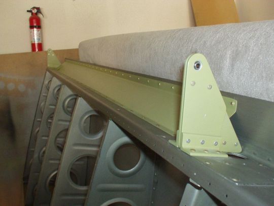
| 2009.09.14:
(0.0) Clecoed the outboard bottom
skin to the left wing and match-reamed the rivet holes to final size
(#40), except for holes that are already dimpled or countersunk on the
wing (1. the main spar, and 2. the skin overlap) which I will ream to
final size in isolation.
Also took the opportunity to fit the flap. First I fit the flap
brace. I had already dressed the edges and primed it a long time
ago, but clecoing it on it became apparent that some massaging will be
necessary to get a good fit. The angles of the flanges are
pretty much dead on for the main portion of the flap brace, but the
short sections at the ends didn't sit quite right because of the
different angle that they attach to the rear spar over the
doublers. Clecoing everything into position would put tension on
the structure and distort the skin. So I clamped the flap brace
to the work bench and carefully adjusted the flange angles. It
only took two iterations of eyeball and trial and error to get it just
about perfect. Now everything can be buttoned up with no stress
and no deformation.
Now to the flap. The flaps themselves were actually completely
assembled at the QB factory, so fitting them to the wings simply means
setting the exact location in attaching the (half) hinge to the wing
side. The span-wise position of the flap is set in reference to
the aileron, so I installed the aileron at what I now consider its
nominal position, with two standard washers and one thin washer on the
outboard side of the outboard aileron hinge. The flap is then
positioned such that there is nominally 1/4 inch (minimum 3/16 inch)
clearance between the outboard edge of the flap and the inboard edge
of the aileron. I set mine to 1/4". The chord-wise
position of the flap is set so that nominally its trailing edge
matches the trailing edge of the aileron while in the neutral
position. Some builders have reported problems with this,
stating that a wider hinge had to be used to set it sufficiently aft
without violating the edge clearance requirements. I didn't find
any such problems. The holes ended up smack dab on their nominal
location on the hinge, with edge clearance to spare, and the trailing
edges are dead on. Maybe it was a problem early on and Van's
later fixed it, or maybe I just got lucky. Anyway, all went
well.
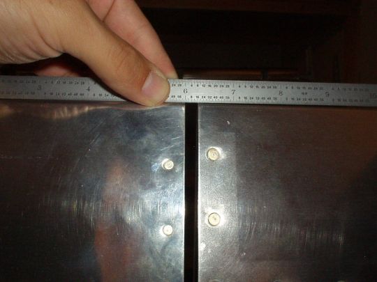 |
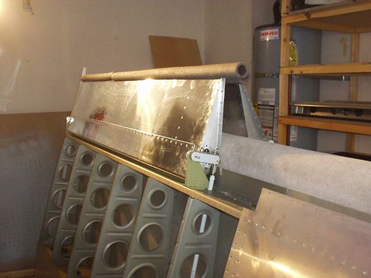
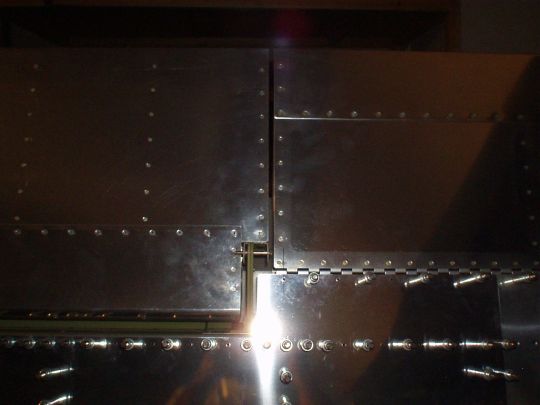
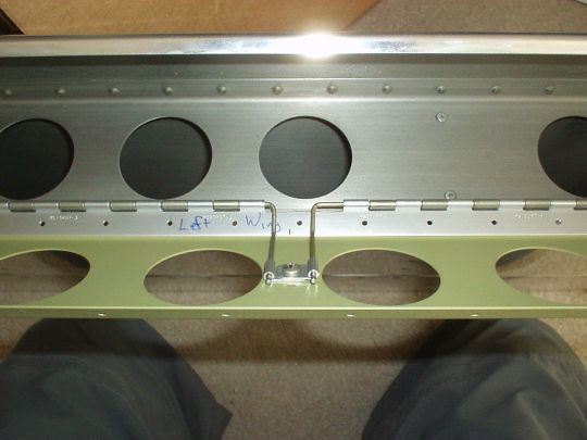
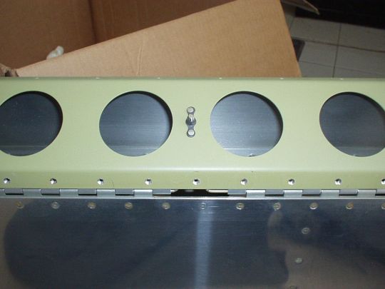
| 2009.11.01:
(0.0) Flap hinge pins: There are
basicall two options for insertion and removal of the flap hinge
pins. 1) Drill a hole through the inboard aileron hinge bracket
so that the flap hinge pin can slide through it, or 2) Remove three
hinge eyelets (one from the wing and two from the flap) in the middle,
and slide in a half-length hinge pin in each direction through the
gap. I chose the latter, and built in a neat arrangement for
securing the hinge pins. A picture is worth 1000 words:
And... I finally riveted the flap braces to the aft wing spar.
By doing this before riveting on the bottom skin, I was able to at
least use solid rivets at the outboard end where the wing bay is still
open. (I also used a solid rivet at the most inboard end).
Now riveting flap brace to the skin and hinge will have to wait until
the outboard bottom skin is riveted on, which will hopefully be very
soon. |
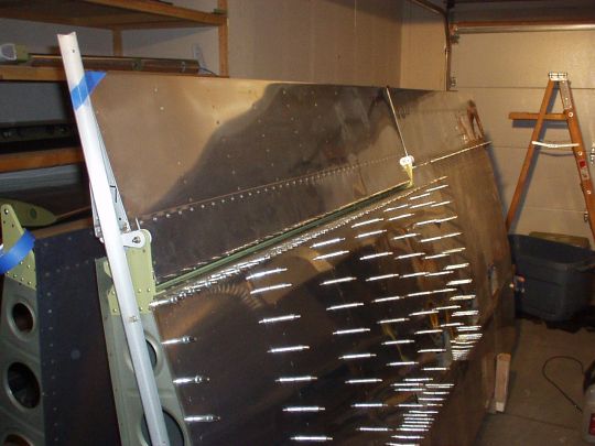
| 2010.01.22:
(0.0) Closed the right wing,
i.e. riveted on the outboard bottom skin. Did this over several
sessions totalling about 8 hours. A big thanks to my riveting
partners: my good friend and flying partner Jimmy for the three
inboard bays, and fellow RV builder John Francis for the three
outboard bays.
In closing out this skin I took a slightly different approach from
Van's normal method. Van's method as described in the manual is
to start with the inboard aft corner, peeling the rest of the skin
away to provide bucking access, and working out toward the outboard
forward corner half a bay at a time. This is fine access-wise,
but what I didn't like about it was the potential for warping and
wrinkling due to uneven distribution of tension in the skin, a fairly
common problem seen on many RVs. My preferred approach was to do
as much riveting as possible with as much of the skin as possible
clecoed (or already riveted) in its proper position on the wing with
any stresses evenly distributed. I still worked generally from
the inboard end toward the outboard end, but with the skin fully
clecoed on the wing most of the time. Following is a summary of
the sequence is used:
1. Cleco the entire skin to wing, taking care to line it up as well as
possible and distribute its tension as evenly as possible.
2. Rivet the three inboard bays while the skin is fully clecoed.
Every rivet in the three inboard bays can be bucked through the access
hatches. [Note that I started by putting in a few rivets along
the main and aft spars in these three bays to "tack down"
the exact position of the skin so it can't creep or shift around in
one direction or another. Only then I filled in the remaining
rivets inbetween, again in such a distributed order such as to not
induce creeping. I use this technique throughout.]
3. Un-cleco the skin from the outboard-most two bays of the wing, as
well as the main spar of the next bay.
4. Rivet the next bay, which has to be done basically by Van's method,
with the skin peeled back from the bays further outboard.
There's just no other access to bucking those rivets. [It would
sure be nice if there was one more access hatch! Then the whole
wing could be done without peeling back the skin!] Here too, I
started by putting in a rivet near the outboard end of that bay along
the aft spar to tack down the geometry. Then filled in the
remaining rivets along the aft spar and along about the aft half of
the rib. I then clecoed along the main spar and riveted the main
spar and the remaining forward half of the rib.
5. Re-clecoed the skin to the entire remaining section of the wing.
6. Rivet the remaining two bays (the outboard-most two bays) while the
skin is fully clecoed. These can be bucked through the oubtoard
end of the wing.
The results look great. The skins look smooth and the tension
feels right and is well matched across all wing bays. I should
have a straight wing.
WORD OF CAUTION: Some serious "yoga" is needed to buck a few
of the rivets using this approach. And I have long skinny
arms. Some folks will surely not be able to do this.
Before committing to it, I did a dry run just to be sure I could reach
all the rivets this way. I strongly suggest that anyone
considering this approach should first do such a dry run themselves. |
| 2010.01.22:
(0.0) Finished closing the left
wing, again over several riveting sessions with help from John F. and
Jimmy. |
|
|