|
  

Angle of Attack (AoA) Instrument
Running Total Hours:
0.0
 | 2009.07.17: (0.0)
Some background: Angle of attack (AoA) instruments are still uncommon
in small general aviation aircraft, but have been in use for decades
on higher performance and especially naval aircraft. Having a
true AoA indication allows the pilot to fly the airplane much more
precisely at high angles of attack than he could by using airspeed as
an approximation. With the AoA instrument the pilot can
consistently pin-point L/D-max, the critical angle (i.e. stall angle),
or any other desired AoA irrespective of gross weight, G load, or
airspeed. This is especially useful in pin-pointing best rate of
climb (Vy), best glide (Vg), max endurance cruise, preventing stalls
in all flight regimes, and flying consistent approaches (all carrier
approaches are flown at fixed AoA, not airspeed).
PSS / AFS AOA INSTRUMENT
So, my airplane will have an AoA instrument. The one I chose was
originally designed by Jim Frantz of Proprietary Software Systems,
Inc. and sold in two variants as a stand-alone product. In 2004
Advanced Flight Systems bought the rights, and has integrated it as an
option to their EFIS products (they also continue to sell the original
stand-alone products). This particular AoA instrument is unique
in that it doesn't require any external veins or probes. It uses
two tiny holes in the wing, one on the top and one on the bottom at
the same percent chord, to measure differential pressure. Dividing
this by the pitot-static differential pressure yields a coefficient of
pressure that varies linearly with angle of attack. The product
documentation is excellent, and explains the theory of operation in
great detail. [Note: one disadvantage of this system is that it
also relies on pitot-static data, and therefore does not serve as an
independent backup for the airspeed indicator, but I can live with
that.]
I'm holding off on the major avionics purchases for now, but still
trying to fit all the remote sensors so I can close up the airframe
structures, in this case the wing. Fortunately, AFS sells their
AoA option in two pieces: the "A kit" containing the
pressure ports and plumbing, and the "B kit" being the
corresponding hardware/software option in the main EFIS box (the
"A kit" is the same for the EFIS-integrated option or for
either of the stand-alone variants). So for now I purchased the
A kit through Stein, and that will enable me to finish up the wings.
PRESSURE PORT INSTALLATION
I decided to install the pressure ports in the left wing, for no
particularly strong reason. Aerodynamically, they could go just
as well in either wing, but I opted for the more direct routing of the
pressure lines to the pilot-side main EFIS box.
The exact location of the ports is per the manufacturer's
recommendation specific for the RV-4/6/7/8. These have been
tested on several aircraft, have been shown to work well, and the
corresponding calibration data is available. The ports are
located in the outer-most wing bay, 6 inches forward of the wing skin
break at the spar (approx 12 inches aft of the leading edge).
Span-wise, the upper port is located 4.75 inches inboard of the edge
of the skin, and the lower port 7.5 inches inboard of the edge of the
skin. Note that I was concerned initially that this location is
behind the duckworks landing light, and the interface between the lens
and skin may interrupt the airflow and affect the pressure at the
ports. However, Rob Hickman of AFS had noted on the AFS support
forum that this has been tested and shown not to be an issue. He
noted that in fact the default calibration data was obtained from
Jerry VanGrunsven's RV-6 that had the landing lights in front of the
AoA ports.
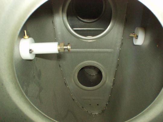
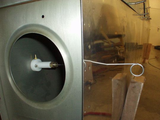
The pressure ports are each implemented with a piece of machined
delrin that attaches to the inside of the skin with two countersunk
#4-40 screws and nuts (and will be pressure sealed with a gasketing
material on final installation). Note that the #4-40 screws
provided with the kit don't appear to be standard mil-spec hardware,
and I'm uncertain of their exact countersink angle. I replaced
them with MS24693-S8 screws that have a 100° countersink angle, and
conveniently very close to the same head dimensions as an 1/8 inch
diameter AN426 rivet. Still, the diameter of a #4-40 screw shank
is
considerably smaller than 1/8 inch, but that's no problem. I
found a good way to drill and dimple the wing skin for these
screws. Drill the holes to #34. A #4-40 screw will just
barely slip through that hole, and so the delrin part can be screwed
into the first hole and then used as a guide for precisely positioning
the second hole. After both holes are drilled, they are dimpled
using a pair of dimple dies that are pulled with a pop-rivet puller
tool (not to be confused with 120° pop rivet dimple dies, these are
100° dimple dies meant for solid 1/8" rivets). These
1/8" solid rivet 100° dimple dies are available for about $10
from Wicks. The nails that are provided with the dimple dies for
use as a puller shank are actually quite smaller than 1/8" and
fit easily through a #34 hole. The dimpling process enlarges the
hole slightly so a #4-40 screw now slides through it easily, and the
dimples fit the MS screw heads quite nicely.
The actual pressure taps are drilled with a #60 bit. The tiny
hole size is reportedly sufficient, and effective in keeping the bugs
out and even the rain.
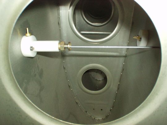
Still, the upper pressure port has potential for water infiltration,
so the delrin part is designed as an air-water separator, essentially
a water trap beneath the air pressure nipple. The water trap has
a spring-loaded drain (like those used on fuel sumps), but it is
located inside the wing to keep the installation simple and minimize
added drag. The drain is accessed by poking a stick through
another small hole drilled in the bottom wing skin. The poker
(provided) is 0.092" thick, and I drilled the hole to #40.
Note that the hole is obviously at the same span-wise position as the
upper port, but is about 3/16" further aft than the chord-wise
position of the ports. That is to place on-axis with the upper
port, considering that the upper and lower wing skins are not in
parallel planes to each other.
|
|
|