|
  

Autopilot
Running Total Hours:
0.0
 | 2009.05.04:
(0.0) I decided
early in the project that I will install a 2-axis autopilot.
Before going into further detail, let's get some basics out of the
way.
WHY AN AUTOPILOT
Several people, both pilots and non-pilots, have asked me: "Why
would you want an autopilot? Isn't the whole point of this
airplane that you will enjoy flying it?" Fair
question. First of all, yes, the main purpose of this airplane
is that I'll enjoy flying it. But "flying it" doesn't
exclusively mean "stick-and-rudder flying it". The
RV-7A has flying characteristics that make it a very fun
stick-and-rudder airplane, but it is also a very versatile airplane,
and an autopilot helps make full use of that versatility. More
specifically, the RV-7A's handling characteristics are light and
quick, which is a lot of fun, but also requires a high level of
attention from the pilot to maintain a desired flight attitude,
heading, and altitude. These handling characteristics are ideal
for fun VFR flight and sport aerobatics, which are at the center of
its mission profile. But the airplane is also generously
"long-legged" such that cross country travel and IFR
operations are also among its primary missions. On long cross
country flights, and especially in IFR, those same handling
characteristics increase the pilot's mental workload and
fatigue. An autopilot allows the pilot to temporarily offload
the task of physically controlling the aircraft in order to tend to
other tasks, which is a great asset at certain times during a flight.
WHY A 2-AXIS AUTOPILOT
The Warrior that I currently fly has a single axis autopilot, roll
only. This autopilot can hold a heading, and even track a course
on a VOR, ILS, or GPS receiver. But it has no control over
pitch, which makes it mostly useless in practice. In perfectly
smooth air, one could, in theory, perfectly trim the airplane and
expect it to hold altitude. But reality doesn't usually work out
that way, and especially in bumpy IFR conditions when the autopilot would be
of most value. My experience has been that having to manually
control pitch but not roll does not significantly reduce my workload compared to manually controlling both, especially if there's any
turbulence at all. Nor does it free up my hand. So that's my final
verdict on single-axis autopilots. Mine will be a 2-axis
autopilot (pitch and roll), which will afford me true hands-off flying
when it's engaged.
So why not 3-axis? What about the rudder? Well, the
RV-7A's ailerons exhibit so little adverse yaw under normal cruise
conditions that sufficiently coordinated flight, including standard
rate turns, can be maintained even without rudder inputs. So
within the autopilot's operating envelope, it can get by without
rudder control. So 2-axis is sufficient, mostly. The
"mostly"
is that the rudder should still be in trim for coordinated flight for the steady state flight
condition. This I plan to achieve using a separate rudder trim
system of my own design (none is included in the stock
airframe). I may even provide for automatic control over it
using AHRS data, but that'll be further down the road. |
| 2009.06.27:
(0.0) I settled on
a TruTrak 2-axis autopilot. Why TruTrak? TruTrak's line of
autopilots is the best in class (in fact just about the best there is)
in performance and reliability, and has a long proven track record in
hundreds if not thousands of aircraft. A full line of control
heads is available from the most basic to full featured, and the
company offers a very flexible upgrade option. The TruTrak
autopilots also integrate very well with a variety of other avionics
(including Advanced Flight Systems EFIS), but are not dependent on
those avionics and are capable of operating stand-alone.
TruTrak, run by the legendary Jim Younkin, also has earned a solid
reputation for standing behind its products, which by the way are all
under lifetime warrantee.
I purchased just the servos for now through SteinAir. The servos
will work with any of TruTrak's 2-axis autopilot heads, including the
upcoming Advanced Flight Systems customized version of the TruTrak
DigiFlight II VSGV, which is my current plan. The servos
themselves are TruTrak's "B" size servos, which are the
smallest ones, and are what's generally used for the 2-seater
RV's. The "B" servos have a torque rating of 30 in-lb,
and a residual torque (i.e. inactive resistance) of approximately 0.8
in-lb. The roll servo is a standard servo, and the pitch servo
is a version that has a trim sensing feature. The servo purchase
also includes all the necessary mounting hardware to install the
servos in the RV-7A. The pitch servo sits just aft of the
elevator bellcrank in the aft fuselage, and the roll servo sits just
outboard of the aileron bellcrank in the wing. Both servos
connect to their respective bellcranks using small pushrods. I
opted to mount the roll servo in the right wing for better lateral
balance, but installation hardware is available for either wing. |
| 2009.07.10:
(0.0) I received
the servos and installation hardware. Everything appears well
designed, robust, compact, and elegant.
I did encounter a couple of issues though upon closer
inspection. The pitch servo had a small "ding" in the
housing, as if it had been dropped or slammed against a hard
surface. The ding was pretty small, but it did prevent the servo
from sitting flush against the mounting bracket. It also was
cause for concern about the possibility of the servo having suffered
internal damage by the same event that caused the ding. I don't
have the control head yet, so I have no way to test the servo.
But also, the servo arm exhibited a fair amount of free play, both
rotational and in-out. This is true of both servos, but much
more so on the dinged pitch servo, so that also caused me
concern. I spoke with Paul at SteinAir about it, and he
instructed me to return the servo for a replacement. I did, and
a new one is on its way. After the servo in question had arrived
back at SteinAir, I spoke with Stein about it. He indicated that
the amount of free play in the servo arm was normal, that the
trim-sensing pitch servos always have more free play than the standard
roll servos. And he would have suggested that I simply file down
the ding and retouch it with an alodine pen. I would have
actually been ok with that, so long as it wouldn't affect my
warrantee. But anyhow, a new servo is already on its way, so
that's that.
The installation hardware for the RV-7 is well designed, simple and
robust. All very straight forward, but just a few minor gotchas
worth noting:
Gotcha 1: The accompanying drawings, which are annotated to be 1:1
scale, were actually printed slightly scaled down. However,
they're also available as PDF's on TruTrak's web site, and I was able
to print them out myself at the correct 1:1 scale. Anyway, this
only matters for setting the roll servo pushrod length, which does not
have a dimension call-out on any of the drawings.
Gotcha 2: The drawing for the pitch servo installation shows the
F-729A rib having its lower flange on the starboard side, whereas in
fact it is on the port side. The drawing was originally done for
the RV-6, so maybe that's the source of the discrepancy. Anyway,
not a problem. The servo mounting bracket still installs on the
starboard side of the F-729A rib, opposite and F-729A's bottom flange,
and the mounting bracket's bottom flange gets riveted directly to the
bottom skin.
Gotcha 3: The install hardware includes most of the necessary
fasteners (not quite enough washers), but the stack-ups of washers,
etc. are nowhere shown on the drawings or any of TruTrak's other
documentation that I could find. Another builder on the VAF
forum posted that he had obtained this information from TruTrak by
phone. Unfortunately he then didn't list the stackups, but he
did post a couple of photos that show it, more-or-less. It
appears to be as follows:
- The servos are fastened to the mounting brackets with an AN3H-3A
drilled-head bolt, AN960-10 standard washer, through the mounting
bracket, and into the threaded mounting hole in the servo. Then
the bolt heads should be safety-wired.
- Pitch servo arm to push rod (left to right): AN3-7A bolt, servo arm,
rod end bearing, AN970-3 large diameter washer, AN364-1032A thin nut.
- Pitch servo push rod to elevator bell crank (right to left): AN3-10A
bolt, AN970-3 large diameter washer, rod end bearing, two AN960-10
washers, elevator bell crank, AN960-10 washer, AN364-1032A thin nut.
- Roll servo push rod to roll servo arm (top to bottom): AN3-6A bolt,
AN970-3 large diameter washer, rod end bearing, servo arm, AN960-10
washer, AN364-1032A thin nut.
- Aileron bellcrank to roll servo push rod (top to bottom): AN3-12A
bolt, aileron bell crank, 0.523" aluminum spacer (parts list says
0.563", but actual measured 0.523"), rod end bearing,
AN970-3 large diameter washer, AN364-1032A thin nut.
I will likely tweak these stackups slightly, but that's a good
starting point.
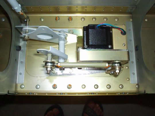
ROLL SERVO INSTALLATION
The roll servo mounting brackets couldn't be easier to install -- they
simply bolt on at the location of Van's standard aileron bellcrank
brackets. (These appear to be cadmium-plated steel, but I will
still likely give them a coat of epoxy primer for increased corrosion
protection).
Measuring from the drawings, I came up with a pushrod length of
4-7/8" bearing center to bearing center, which in fact worked out
perfectly. When the aileron bell crank is in the neutral
position (determined using the aileron bell crank jig), the servo arm
is right at the 12 o'clock position, i.e. 90° to the pushrod.
The aileron bellcrank can also be swung all the way in either
direction (until it hits the wing spar in one direction, or hits the
servo in the other direction) without binding or over-centering the
pushrod geometry. The actual range of motion will be far less,
as limited by the aileron stops, but it's nice to know that the servo
installation is safe from over-centering or any other binding issues
well beyond the ailerons' maximum throws.
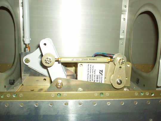
Above: neutral ailerons (notice the aileron bellcrank jig).
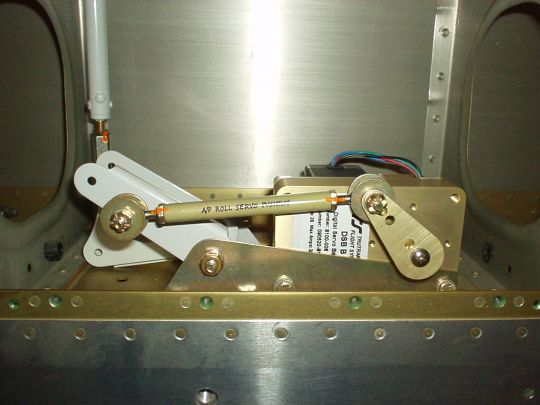
Above: extreme right ailerons, well beyond aileron stop (notice
aileron bellcrank hitting the spar web).
Above: extreme left ailerons, well beyond aileron stop (notice the
aileron bellcrank hitting the servo).
I also decided to modify the fastener stackups slightly to get better
alignment, and better security. The new stackups are:
- Roll servo push rod to roll servo arm (top to bottom): AN3-7
drilled-shank bolt, AN970-3 large diameter washer, rod end bearing,
AN970-3 large diameter washer, servo arm, AN960-10 washer, AN310-3
castle nut, AN380-2-2 cotter pin.
- Aileron bellcrank to roll servo push rod (top to bottom): AN3-13
drilled-shank bolt, aileron bell crank, 0.523" aluminum spacer,
AN970-3 large diameter washer, rod end bearing, AN970-3 large diameter
washer, AN960-10 washer, AN310-3 castle nut, AN380-2-2 cotter pin.
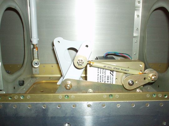
Above: view showing the pushrod fastener stackups (and my toes).
Note that the large diameter washers are playing the role of
"capture washers", which is standard practice when it comes
to rod end bearings (although Van's doesn't always adhere to
it). Their job is to retain, or "capture", the rod end
in the unlikely event that the bearing fails catastrophically and
disintegrates.
PITCH SERVO INSTALLATION
The pitch servo mounts to a bracket (provided by TruTrak) that is
riveted to the ... |
|
|