|
  

Wing Attachment / Rigging
Running Total Hours:
0.0
 | 2010.03.13:
(0.0) The wing attachment
rigging is specified as follows:
| Dihedral: |
+3.4° (measured, not specified
anywhere that I've seen) |
| Sweep: |
0° (Van's states that ±1/2 inch
at the wing tips is plenty close enough) |
| Incidence: |
+1.0° (relative to the main
longerons) |
The dihedral angle is
pre-set by bolt holes through the main wing spar and fuselage center
section bulkhead that were drilled in a jig at the factory.
Sweep and incidence are then set by one bolt connecting the rear
wing spar to a fork eminating from the corresponding bulkhead in the
fuselage. This bolt hole has to be drilled by the builder, i.e. me, with
everything jigged and clamped in the exact correct geometry. It
is also critical that the edge distance requirement be met for this
hole though both the spar and fork. All simple in principle
but fairly involved in practice, and there are no "do-overs"
here, or at least not without replacing major structures in both the
wing and fuselage. So this is definitely a case for measure
twice (or twenty times!) cut once. |
| 2010.03.16:
(0.0) Before fitting the
wings to the fuselage, the inboard end of the rear wing spar has to be
trimmed based on a template found in DWG 38. The reason for this
is that the same wings are used on both RV-7 and RV-8, but the rear
spar mating geometry differs between the two. I've already done
this a while back, and it is documented
on the Wings page.
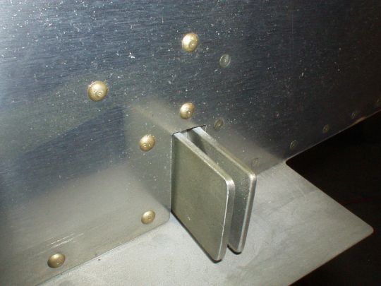
Still, there is a common problem with the fit in this area reported by
many builders. The problem is that a universal (i.e. dome head)
rivet on the fuselage skin right above the rear spar fork interferes
with the rear spar, not letting it come sufficiently inboard, and
therefore causing a slight forward sweep. There are basically
three options on how to deal with this: 1) live with a slight forward
sweep, 2) trim the spar further to remove the interference, or 3)
replace the universal rivet with a flush rivet. I decided to
just take care of this problem upfront before even attempting to fit
the wings, and I opted for option number 3. Of course it would
have been trivial to use a flush rivet in the first place when
building the fuselage, but until Van's takes 5 minutes to change the
rivet callout on the plans, builders (and especially QB builders) will
continue to have to find and deal with this problem after the
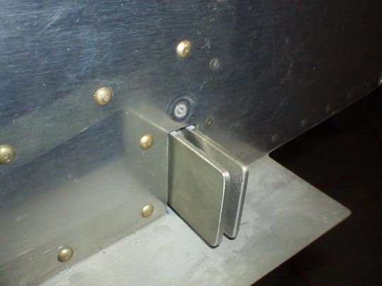
fact. Argh... I drilled out the rivets and replaced them
with CherryMax flush rivets (CR3242-4-2). The CR3242-series
rivets have a slightly oversided shank diameter, which allowed me to
enlarge the hole to #27, thereby cleaning up the deformed hole that
was left after removing the original rivet. Dimpling the holes
was a bit tricky too because the stackup is thick (2 x 0.032"),
and because the backside of the hole is under the seat pan. But
I got it mostly dimpled using a puller-type dimple die, and then
cleaned up the dimple just a touch with a machine countersink
bit. End result is ok. Just too bad about having to spend
a couple of hours on something like this.
Before (as assembled by QB factory according to the plans):
and after:
 |
| 2010.04.10:
(0.0) Close tolerance bolts
are used to connect the main spars to the carrythrough fuselage
bulkhead. These form a very tight fit (perhaps even an
interference fit?), and therefore are not well suited for repeated
insertion and removal. Van's recommends that garden variety
"hardware store" bolts be used for the initial fitting, so
that's what I'll do.
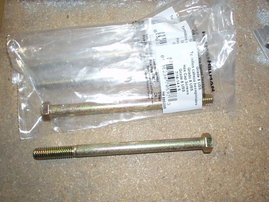
The big bolts have a 7/16" diameter, which as it turns out is
somewhat rare at the hardware store. Home Depot had plenty of
3/8" and plenty of 1/2" bolts, but no 7/16".
Lowe's on the other hand had the perfrect bolt: 7/16" nominal
diameter (measured 0.4305" actual), 6" long total with
4" shank, i.e. only 2" of thread. These are SAE grade
8 bolts (not that it matters here), and cost about $2 each. The
diameter is a few thousands smaller than the close tolerance bolts, so
it makes for a comfortable slip fit (note).
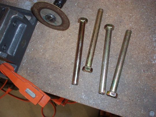
As for length, I cut off the threaded portion and ground a smooth
taper on the end, leaving effectively a 4" pin. The stackup
of the bulkhead and wing spar is only about 3", so I don't have
to insert the pins all the way to the head, and therefore they should
be easier to remove.
Note that there seems to be a very slight
misalignment between the forward and aft carrythough bars on the
bulkhead. This is almost undetectable on the starboard side, but
a bit more pronounced on the port side, making it slightly harder to
insert the bolts. I suspect that this won't be an issue and the
bolts will pull everything into place, but this is on my radar as a
possible issue on the horizon. |
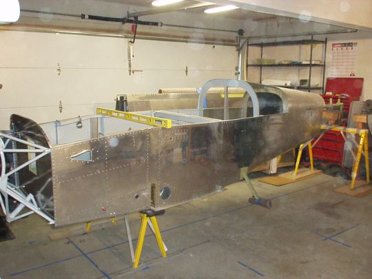
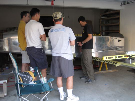
| 2010.04.13:
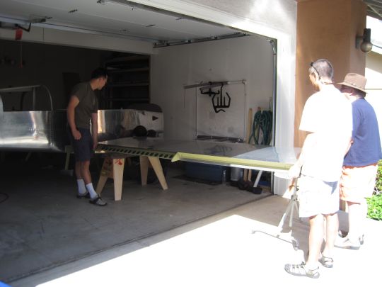
(0.0) Big picture strategy:
My two-car garage is plenty big enough to complete most of the
project, but it is still too small to have both wings on the fuselage
simultantously (a three-car garage would be so nice! Sigh...).
Although some people have set the incidence and sweep one wing at a
time, I think it would be much better to have both wings on
simultaneously to ensure symmetry, which is more important than
individual accuracy. After considering many different options,
including moving to a different location (i.e. airport hangar), I
decided to keep it in the garage and use the following strategy:
Rotate the fuselage 90° from its current orientation, such that its
starboard (right) side faces the garage door and its port (left) side
faces the kitchen door. Position it such that there is just
sufficient space for the left wing to be mounted to the
fuselage. The right wing, when mounted, will protrude through
the garage door by about two feet. The idea is that I can put
the left wing on and leave it indefinitely (i.e. be able to close the
garage door). Then in one marathon day, put the right wing on in
the morning, with both wings on set the incidence and sweep (i.e.
drill the rear spar attach points), and then remove the right wing by
evening so I can again close the garage. After the rear spar
attach points are drilled, I can perform all remaining wing-fitting
tasks one wing at a time with no need for the other wing to be mounted
to the fuselage. So I'll then complete the left wing fitting
tasks at my leisure. And when that's done, I'll remove the left
wing, shift the fuselage by a couple of feet away from the garage door
such that there is sufficient room for the right wing, re-mount the
right wing, and then complete the right wing fitting tasks at my
leisure.
Down to it.
So to start, I cleaned up the garage some and made room to rotate the
fuselage. One big object I had to deal with was the crate that
the finish kit arrived in. This thing was 8 ft x 4 ft x 2 ft,
and was taking up a lot of room. I had been using it for
storage, and its top as workspace, but now it was time to say
goodbye. I though I'd have to chop it up and haul it to the
landfill, but on a long shot I decided to advertise it as free for the
taking on Craig's List. I posted it around midnight, and by
morning I had about a dozen responses. Who would've
thought? I gave it to the first guy who responded, who is now
using it to haul dirt and other building materials on his
trailer. It was a perfect fit, like it had been built for
it. Interestingly, he told me his dad was also a veteran
EAA'er. Small world!
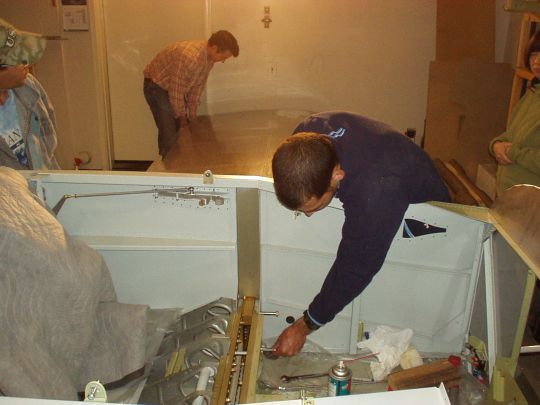
Back to business. With the garage floor now clear, I marked the
positions that the saw horses will take for the fuselage to land in
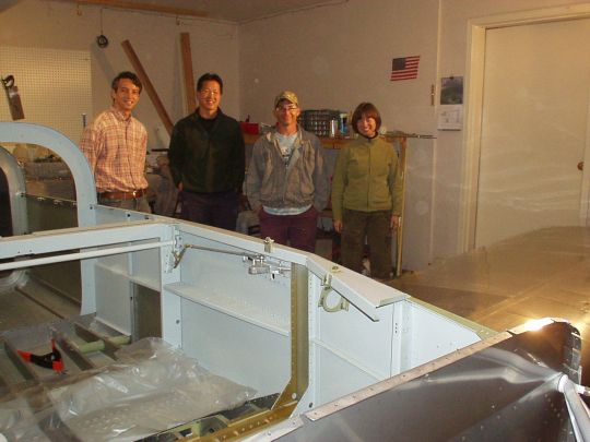
the right place. And then tonight my friends Jimmy Y, Chris B,
and John N came over and helped me rotate the fuselage. We then
also leveled it, both longitudinally and laterally (i.e. in pitch and
roll). Note that the garage floor slopes toward the garage door
at about 0.6°, and so shims had to be used under the right-side legs
of the sawhorse under the center section to level it laterally.
Then we added shims under the saw horse supporting the tail in order
to level the fuselage longitudinally. It all went well.
Things sure go easily when you have good help. Thanks guys!
We also brainstormed about the next phase, how best to get the left
wing from the wing cradle on the right side of the fuselage (garage
door side) over to the left side of the fuselage (kitchen side).
I was initially planning to just carry it out the garage door, around
and through the house, but John had a good suggestion of using moving
dollies to just slide it right under the tail cone. Less risk of
dinging the wing going around a corner. Great idea! |
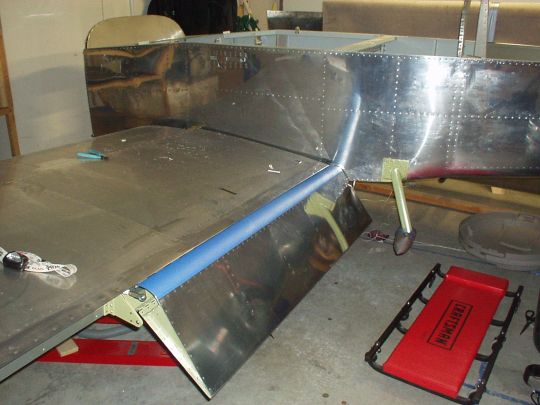
| 2010.04.19:
(0.0) Tonight the guys came
over again, and with their help and Stacey's, we got the left wing
mounted. To get it over to the left side, we used furniture
dollies as John suggested. That worked out great. First,
as an easy way to get the wing off the cradle and onto the dollies in
the right position (root and tip, right under the main spar to prevent
skin damage), we just duct-taped the dollies onto the wing in position
while it was still in the cradle. It was Chris's idea to use
tape to mark the location of the dollies on the wing, a great
suggestion, and the idea then quickly evolved from there. It was
a tight fit as expected (I measured everything earlier, and left only
a few inches margin), but we got the wing over to the left side and
onto a pair of padded saw horses that I had prepared the day before.
I lubed up the main spar and bulkhead (as well as the 7/16" pins)
with LPS-2, and finally now it was time to slide the wing into the
fuselage. It was a tight fit (as it should be) and it took some
very precise maneuvering, but in a few short minutes we got it in
place and put two pins through the bulkhead and main spar. I
positioned a padded saw horse under the outboard section of the wing
to make sure the fuselage doesn't tip over, and now it was time to
just stand back and admire our work (followed by Mexican food and
beer!). Wow, with a wing on it, it sure does look like an
airplane. Thanks again to my trusty crew!
P.S. It should be noted that this operation was not entirely without
casualties. No airplane parts were harmed, but the crew and I were
harassed and dined upon by mosquitos and an assortment of other bugs
throughout the whole operation. Ouch!
 |
| 2010.04.22:
(0.0) Checking incidence
and twist (preliminary):
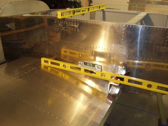
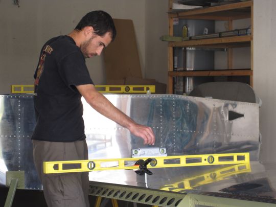
With the left wing now temporarily mounted to the fuselage, I thought this would be a good time to do a preliminary check of incidence and twist. Per Van's instructions and plans (DWG 38), wing incidence should nominally be set to +1°, and this is determined as follows. With the fuselage level (reference is the upper longerons), achieve level between a point on top of the wing right over the main spar web, and the point three inches over the rear spar web at the same span.
To clarify, when the line between these two points is level, i.e. 0°,
the wing incidence is set correctly to +1°.
Note that if the wing has zero twist, as ideally it should, then
the incidence measurment will be identical at any span-wise location.
It is also important to note that the absolute accuracy of the angle of incidence is less critical than having a close match between the angles of incidence of both wings, since any relative difference in incidence will mean a relative difference in angle of attack. A relative difference in wing incidence would lead to asymmetric flying qualities, "heavy wing" that must be held up with aileron, a stall that wants to fall off in one direction, etc. And there is no good way to fix it after the fact. On the other hand, if the absolute angle of incidence of the wings is different from nominal but they have a
good relative match, then an identical adjustment can be made to the angle of incidence of the horizontal stabilizer to preserve the relative incidence between it and the
wings, thereby preserving the intended flying characteristics.
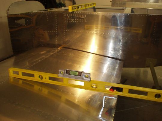
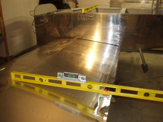
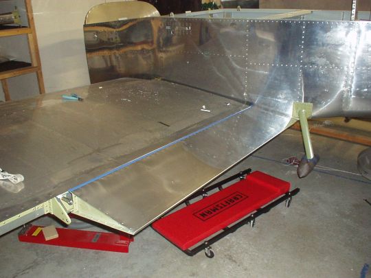
I took a few steps to make the wing incidence measurements easy and repeatable/precise:
1. I measured the distances between the edges of the skin and the spar webs, which are of course not visible from the top of the wing. I found that the forward spar web is 1 inch forward of the butt joint between the forward and aft wing skins, and the rear spar web is 2-7/8 (2.875) inch forward of the aft edge of the aft wing skin. These measurements should be fairly accurate, but more importantly, they will be used consistently throughout the process, thereby ensuring precision, which is more imporant here than
accuracy as explained above.
2. Using these distance measurements, I marked the main spar and rear spar lines at several locations on the top skins of the wing. I also marked fore-aft lines that intersect the main and rear spar lines at matching span-wise locations (I used the wing rib rivet lines to make it accurate and easy). I did this at four different span-wise locations that were roughly equidistant from each other: near the wing root, near the wing tip, and at approximately 1/3 span and 2/3 span. So this gives me four main spar / aft spar point pairs that I can use to measure incidence.
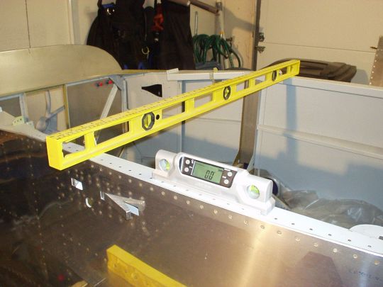
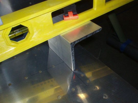
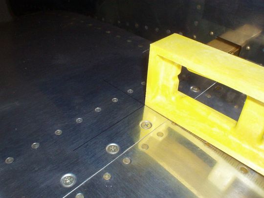
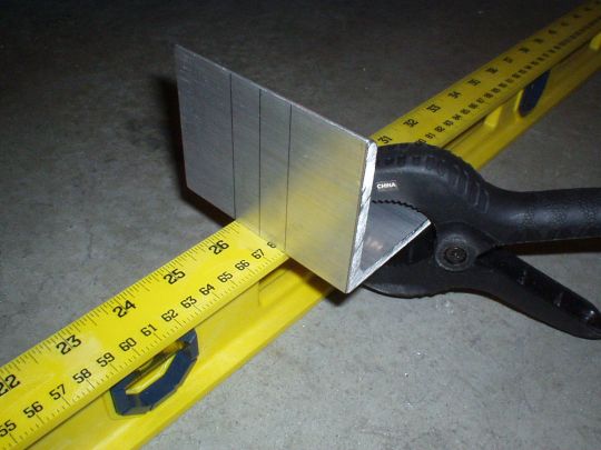
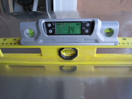
3. As for the level and the three inch stand-off, I devised a simple contraption. I used a 48" bubble level ($10 at Harbor Freight) and some 3" x 3" aluminum angle ($10/ft out of the scrap bin at Industrial Metal Supply in Kearney Mesa). I cut a 4" length of the Al angle (4" is arbitrary, just for stability) and clamped it to the bubble level such that when the edge of the Al angle rests on the rear spar line, the forward edge of the level rests exactly on the main spar line. It worked out that the edge of the Al angle is 26-11/16 (26.6875) inch from the forward edge fo the level.
4. These 48" bubble levels (I have two) are actually of decent quality and yield consistent measurements between each other and when flipped around. However, the accuracy and precision of reading a bubble level is somewhat limited, and even more so when it can only be viewed at an angle. So the 48" bubble level will actually serve not so much as a level but
just as a straight beam. The actual measurments will be taken with my
7" digital level (Craftsman model number 48295), placed on top of the 48" bubble level. The digital level reads in 0.1° resolution, and when taking a series of level measurments in a single session it should be precise to within approximately 0.1°.
So now armed with all this, I re-checked that the fuselage is level, and then measured the incidence at the four span-wise locations that I marked earlier on the wing. All five measurements: 0.0°. So the left wing has no measurable twist (excellent!) and it naturally wants to rest at the correct incidence angle (also excellent!).
 |
| 2010.05.08:
(0.0) This is the big day
-- drilling the rear spars.
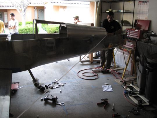
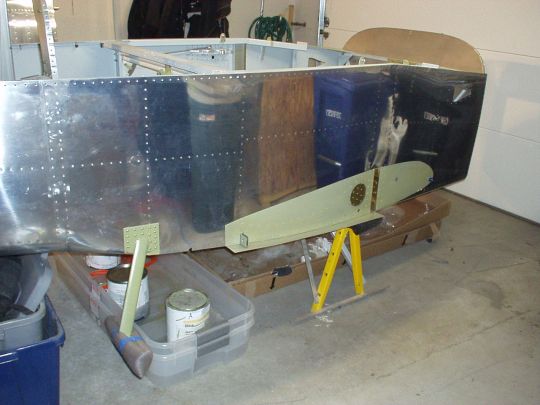
09:00 Putting on the right wing.
The morning crew arrived (John F, Vay, and Jimmy). We quickly got to work, took the right wing off the cradle and attached it to the fuselage with temporary pins. Note how it sticks out through the garage door by about 2 feet. That's why this all has to be done in one marathon day.
10:00 Re-leveling the fuselage.
Their job done, the morning crew is released. And my first task is to re-level the fuselage. I had leveled it previously, but settling with the weight of the wings, it needed some slight adjustment, easily accomplished with a few tongue depressors as shims under the saw horse legs. The fuselage is now level in pitch and roll. Note that before leveling the fuselage, and for the remainder of today's process, I adjusted the saw horses underneath the wing tips so that they don't actually touch the wings. They're still there "just in case" so the plane can't teeter over, but I don't want them extering any forces on the airframe that could distort the critical measurments.
BTW, I also took a minute to measure the dihedral angle while I had a
chance. Not that I have any control over it, as it was set at
the factory when the wing spars and fuse center section were
drilled. But just to satisfy my curiousity. The dihedral
angle measured +3.4° on both wings.
10:30 First incidence and twist measurements on the right wing.
Time to check the right wing for twist. A couple of weeks ago I was pleasantly surprised to find that the left wing had no measurable twist (less than
0.1°). Alas, with the right wing this was not the case. I found that the right wing does have some measurable twist, and in the less desireable direction (opposite of "washout"). The angle of incidence near the tip is approx
0.15° greater than at the root (a height difference of about 1/16" at the rear spar relative to the main spar). While this isn't happy news, it is actually less surprising than the "perfect" left wing, and is still well within tolerance (Van's states that
a height difference of up to 1/8 inch at the rear spar is common and is not a problem).
Reading through the message boards, I found that most people deal with their wing twist by simply using the mean average incidence of the wing (i.e. incidence at half of the wing panel span, assuming linear twist) when setting the wing incidence. I decided to take a slightly different approach and use the incidence at approx 2/3 span of the wing panel. My reasoning has to do with neutralizing the roll moment. The effective roll lever arm of a section of wing gets bigger the further ouboard it is, and as such, so does the roll moment it exerts on the airplane for a given lift force. Doing the math, it works out that the ideal span to use when matching the incidence to the opposite wing is at about 98 inches from the fuselage center line, which equates to a point at about 2/3 of the wing panel's span. The assumptions/appximations that went into the calculation are that the wing panel extends from span of 22 to 132 inches (including 12 inches equivalent span for the tapered fiberglass tip), that the twist is linear over that span, and that the lift differential is proportional to the incidence differential.
This is all probably way too nit-picky over such a small amount of twist, but I figured I may as well make the best of it that I can.
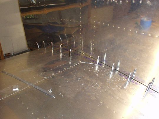
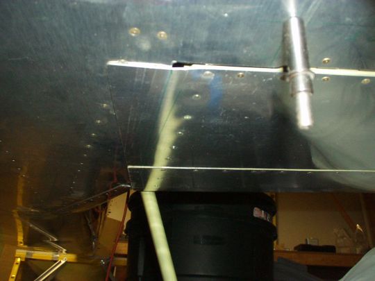
11:30 First sweep angle measurements.
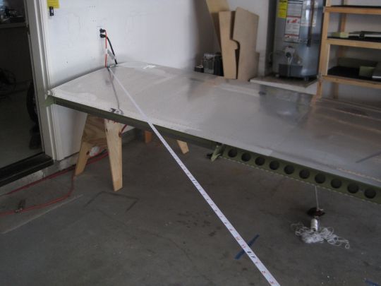
Now I proceeded to check the sweep angle on both wings (specified as zero sweep nominally, with tolerance of +/- 0.5 inch at the tips). Sweep is checked using two complementary techniques:
1. Triangulation to establish sweep symmetry, i.e. that the sweep angles of both wings are identical to each other. I used a soft measuring tape reel to measure distance from identical points at the wing tips to identical points at the tail. To make this an easy and accurate one man job, I used a cleco, a washer, and a couple of small nuts as spacers to create an anchor point for the plastic loop at the end of the measuring tape at the wing tip. I chose one of the pre-punched wingtip attach holes in the upper wing skin, two holes aft of the main spar. I then pulled the measuring tape taught through the air over to the corner of the fuselage skins at the forward edge of the aft deck. I also took a second measurment, pulling the tape to the aft edge of the fuselage skin just below the longeron, just for good measure. I could easily maintain 1/32 inch of precision on these measurements and match the two wings to within that level of precision.
2. A taught lateral string (as a "chalk line") and four plumb bobs at the wing leading edges to establish co-linearity, i.e. that the leading edges of both wings, if projected down onto a level floor, would both lie on a single straight line. I first hung a pair of plumb bobs over the leading edges at identical points near the wing tips, ensuring that they hang down by the same amount. This I accomplished by first marking their strings at identical lengths from the plumb bobs, and lining up those marks with the seam between the forward and aft top skins. BTW, attaching the strings to the wings was beautifully low-tech: duct tape. Ok, now having these two plumb bobs in place, I hung the "chalk line" string such that it intersected the points of both plumb bobs (well, really just a hair underneath so they don't touch, picky picky...). By doing this, I ensured that the "chalk line" string is also level, which in theory is not necessary, but in practice would help keep things getting too far out of whack in case of slight error in the leveling of the fuselage. I hung the string by fishing it through a pair of tongue depressors with small holes drilled in them. The tongue depressors were then clamped to a pair of saw horses near the wing tips. Lastly, I hung two more plumb bobs over the leading edges near the wing roots, which ideally should perfectly point to the "chalk line" string, indicating that the downward projections of the leading edges are co-linear.
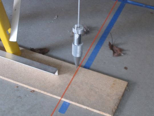
Neither of these techniques alone would actually indicate zero sweep, but together they do. If the leading edges are co-linear AND the sweep angles are identical, THEN the leading edges must be perpendicular to the longitudinal center line of the fuselage.
So with this in place, I started taking some measurements and making adjustments. Long story short(er), I found that the rear spar stubs of both wings, which I had trimmed previously according to DWG ??, were still just a smidge too long to allow the wings to come back far enough to get zero sweep. They were coming in contact with the fulseage skin above the fork, which was keeping them from going any deeper. It proved a good thing, by the way, that I replaced those two universal rivets with flush rivets, because the universal rivets would have made this interference much much worse. In any case, as is now, I found that I could get the wings back to a only very slight forward sweep of about 5/32 inch at full span, which is well within Van's specified 1/2 inch tolerance. I could have taken the wings off, filed another smidge off the spar stubs, and have gotten my perfect zero sweep. But after a brief deliberation with myself, I decided to take a more practical approach, live with that slight forward sweep, and move forward. The deciding factors were 1) not wanting to risk damaging the wings with another cycle of removal and re-installation, 2) my gut agrees with Van on this one that such a small sweep error should have negligible effect on flying characteristics, 3) the sweep error is identical on both wings to within 1/32 inch, so the more important symmetry is maintained, and 4) time to git 'er done!
12:30 Measuring, adjusting, remeasuring...
Now is came the tedium of taking all these measurements, adjusting one or both wings slightly to correct error, re-measure, repeat... It's an iterative process of trial and error. Sweep was actually made easy in a sense, because both wings were bottomed out in that dimension. But incidence is a different story. The wing is flexible enough to easily adjust over half a degree arc of incidence, but the rear spar fork actually forms a very snug fit (impressively close tolerance!), and so there's a lot of static friction to overcome when trying to push the rear spar up and down. It takes a lot of pressure, and when it does finally budge, it tends to move more than the desired amount and overshoot target. So with a little luck and a lot of perseverence, 10th time the charm.
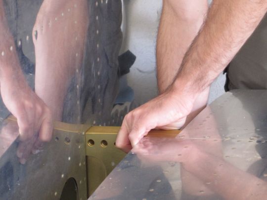
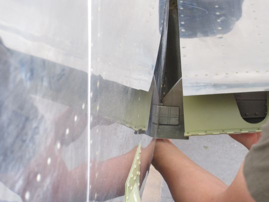
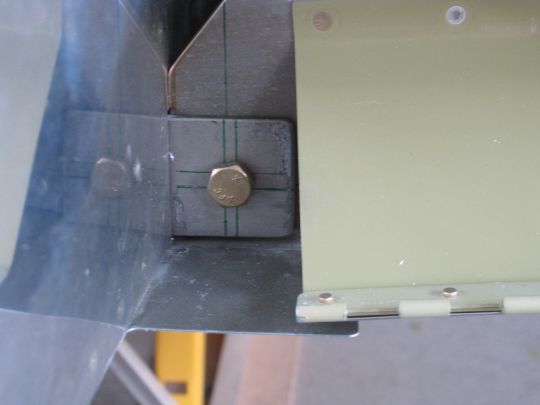
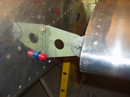
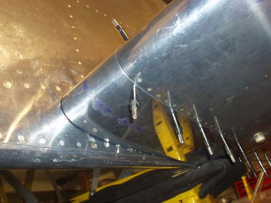
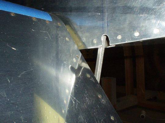
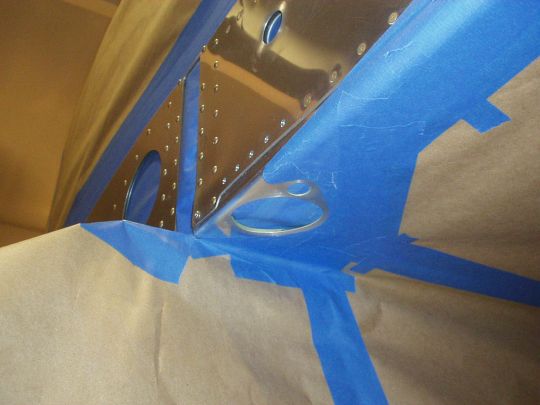
16:30 Checking edge distance, and (gulp) drilling!
Weeks ago, before putting the wings on, I marked the edge distance requirement boundaries on the forks and rear spar stubs. Hole center to edge distance of 5/8 inch (two hole diameters) has to be maintained with both the wing spar stubs (limiting the inboard and bottom edges) as well as the fork bars (limiting the ouboard, top, and bottom edges). This is a big deal. Meeting this requirement IS possible here, but with very little margin. And if gotten wrong, there is no second chance. Not without R&R'ing major structures in the wings and fuselage anyway, which would be a real nightmare scenario and easily months of lost work. This attachment point being as structurally critical as it is, I'm taking the edge distance requirement very seriously.
The usable edge clearance window was narrow enough even in the ideal (less than a 3/16 inch square), so today I was glad to find that at least I still had most of that window to work with. Rear spars clamped in final position, I marked and center-punched the locations of the holes on the aft side of the forks in the approximate center of the available window.
[Note that the following photo was taken earlier in the day when we
were just putting the wing on, before I adjusted the wing geometry,
and in the position shown we actually have negative margin, i.e.
cannot satisfy the edge margin requirement. More photos below
show the final position and positive margin.]
And now the moment of truth. Time to pick up the drill.
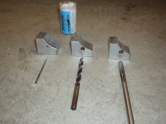
But before I do, a flashback. I've been experimenting over the past week with different methods of drilling the 5/16" bolt holes in the rear spars. The issues are several.
1. Edge distance, as already mentioned, is absolutely critical here. And even starting in the center of a usable window with some positive margin, I have to be very careful to not let the drilling process cause the hole center to drift outside of the available margin.
2. As always, the bolt hole should be perpendicular to the material (the web of the spar and fork). But there is only about a 1.5 inch square of fork web area, and all other nearby structures are either curved or at odd angles, so there is just no good visual reference at all in this area for keeping the drill bit straight.
3. It's very difficult to drill good clean large-diameter holes by hand, i.e. without a drill press. Large diameter jobber bits tend to chatter and wander and bind, and can very easily munge up a hole, leaving it rough, oversized, or oblong.
The best method that I could find to manage these issues was a three-step drilling process: drill a pilot hole with a 1/8" jobber bit, enlarge it with a 9/32" jobber bit, and then to final size with a 0.3105" chucking reamer. It surprised me to find that going straight from 1/8" to 9/32" seemed to work better than using more gradual steps inbetween, but it did. It seemed that the more intermediate steps, the more the hole center would drift, the more concentricity problems would crop up, and actually the more the larger diameter bits would tend to bind and jam. I also could not make use of a unibit to enlarge the hole because the material thickness (1/2" total) was far greater than the step depth of these bits. I tried a few other options, but won't bother to list all the unsuccessful ones. Anyway, I'm very glad that I chose to test these on scrap before doing the real deal.
I also used drill guide blocks to keep the bits perpendicular to the work as I was drilling. I made the guide blocks out of 1 inch thick aluminum bar, and drilled them on the drill press. I made three, one for each bit size. I cut the blocks to size of approximately 1.5 x 1.5 inch to fit over the fork bar, and notched out one corner to clear a clamp that I used to squeeze the fork bars around the spar stub in the top inboard quadrant. I couldn't find a practical way to clamp the blocks to the forks, so I just held them in place with my left hand.
End of flashback.
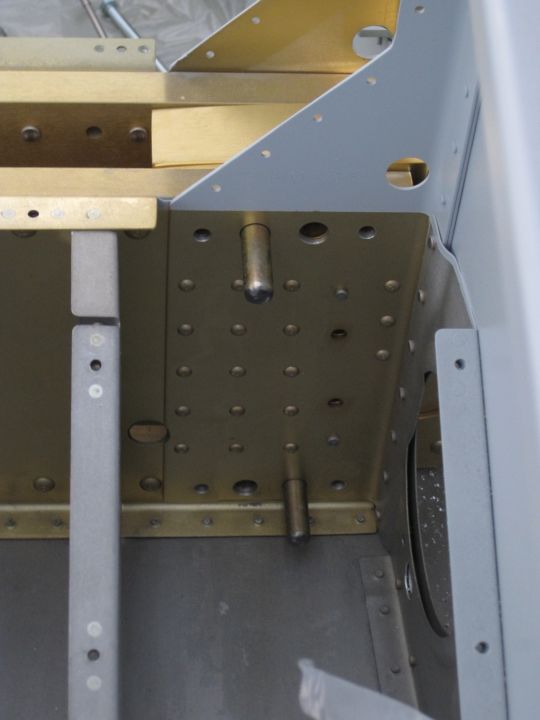
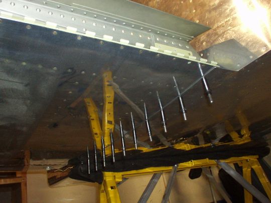
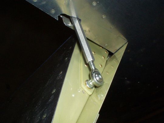
Drilling, drilling, drilling... and re-checking the wing geometry measurements between each drilling step.
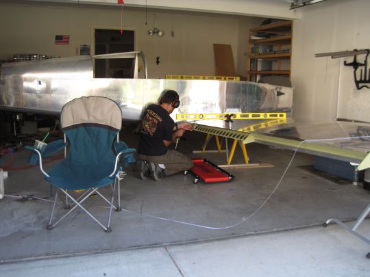
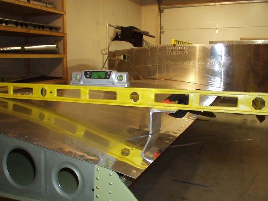
[Note that the position of the level in the photo above is not where
it was to set the incidence, it was further outboard at about 2/3 span
as described above. I had just moved it inboard temporarily to
get it out of the way while re-checking the sweep angle.]
While enlarging the right wing hole to 9/32", I still had some binding issues, but was able to get it done without enlarging the hole to the reamer diameter (the final reamer would still later leave a perfectly round hole). But with the 9/32" bit, right when it finally came through the back side, it grabbed the work and lurched the drill forward, causing the chuck to tear into my left hand which was holding the drill block, and pinning it under heavy pressure between the air drill motor and the fuselage structure. It took a few minutes for me and Stacey to remove the drill and free my hand. Some blood, some lost skin, and a couple of spots of crushed tissue, but no serious or lasting injuries. And thankfully no damage to the airplane (hands heal, aluminum doesn't)! So wash it off, slap on a couple of band-aids, and back to work.
18:00 Almost done...
The evening crew (Jimmy, John N, and Chris B) arrive as scheduled to help pull the right wing back off the fuselage, but I'm still busy drilling. Almost there...
18:15 Done!
Done. And it came out great. The holes are nice and clean and well centered with edge margin to spare. The AN5 bolts slide in smoothly with moderate finger pressure, and have no discernable play -- a good snug slip fit. I re-checked the wing geometry one last time, and confirmed that everything is as it should be. Victory is mine!
We spent a few more minutes savoring an airplane with two wings, and then it was over.
We pulled the right wing, put it back in the cradle, closed the garage, and as is now tradition, went out for burritos and beer at
Jalapeño's.
Thanks again to everyone who helped, or offered to help.
Couldn't have done this one without the crew! |
| 2010.06.01:
(0.0) Now there are more
tasks that can be accomplished with one wing on at a time.
Presently the left wing is on, its geometry held in its final position
with a bolt through the rear spar attach point that was drilled on
2010.05.08.
Fuel tank support bracket
Nothing too complicated here. I had already drilled the bolt
holes in the fuselage long ago. Now the F-796A bracket had to be
adjusted (i.e. bent) slightly to mate flush with the T-405 bracket on
the tank. DWG 38 section E-E shows the approximate bend line,
although the dimensions given are ambiguous. Since it is a 1/2
scale drawing, I opted to simply scale it up on a Xerox machine to
make a paper template for locating the bend line. That got me
very close, and a couple of easy tweaks later I had a perfect fit.
Then, with the F-796A bracket bolted to the fuselage and clamped to
the T-405 bracket on the tank, the bolt hole has to be drilled in the
T-405 bracket. Note that the F-796A has horizontal notch rather
than just a hole for the bolt. This is to allow the bolt to
slide out in the event that the wings are bent aft in an accident, so
that the inboard rib of the fuel tank won't be ripped open. To
match-drill the bolt hole, I used a simple drill guide. I
drilled a 1/4" hole in a block of aluminum, and pounded a
1/4" stainless steel tube into the hole and protruding slightly
past the block on both ends. That allowed me to lay the Al block
flat of the F-796A bracket, while nesting the protruding 1/4"
tube into the notch. I then drilled a perfectly positioned,
perfectly perpendicular pilot hole through the tube. I then
enlarged it to 1/4, and installed the nut plate as shown.
Note that this bolt should be deliberately under-tightened so that it
can slide out as described above. And, it has to be safety
wired. Haven't done this yet, but I'll drill a small hole in the
T-405 for the safety wire.
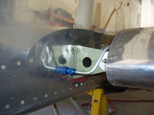
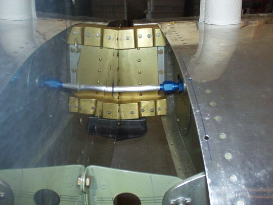
Fuel tank vent line
Fabricated a fuel tank vent line segment that connects the fitting on
the inboard rib of the tank to the fitting on the side of the
fuselage. This is shown in DWG 36A. Again, no magic
here. Just the usual iterative process of shaping and fitting
rigid fluid lines. Note that the tubing clears the tank attach
brackets by about 1/4" to ensure that there is no chance of
contact with vibration and flexing. And likewise, there is more
than adequate clearance from the wing root fairing.
Note that the entire tubing run can be seen in the photo in the
reflection on the side of the fuselage.
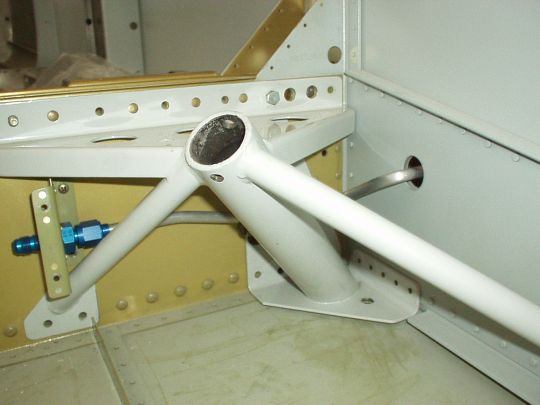
Fuel line
The fuel pickup line in the tank comes out to a bulkhead fitting in
the tank access hatch. From there a line gets routed through the
fuselage side, winds its way through the main landing gear mount, and
as I've laid things out, terminates at another bulkhead fitting at the
F-783B bracket. Long ago I've already fabricated these lines,
except that I had left a long tail on the end that'll mate with the
the bulkhead fitting in the tank access hatch. Now with wing on,
I temporarily reinstalled the gear mount and the F-783 bracket, and
finished fitting the fuel line.
Note that the hole through the side of the fuselage is 1.5 inches in
diameter and about 1/4 inch thick (a sandwich of
aluminum-air-aluminum). This hole can be more-or-less sealed
using a MS35489-99 grommet, which is a somewhat uncommon size, but is
available in small quantities through special order from McMaster.
Wire harness penetration
The wire harness in the wing will be routed through holes that I
drilled previously in the ribs (see
here). Now with the wing on, I slipped a sharpie pen through
the holes in the inboard ribs and marked the corresponding location on
the fuselage side. I will later drill the fuselage side at this
location where the wiring harness will penetrate. I will do this
once the wing is off again.
Bottom fuselage skin and top wing root fairing
The bottom fuselage skin hangs past the fuselage sides and gets
attached to the bottom wing skins, forming a smooth interface.
There is also a single piece aluminum fairing that attaches to the
wing skins, and along with a rubber channel, closes the gap between
the wing root and fuselage all the way around from rear spar, over the
top of the wing, around the leading edge, and back on the bottom to
where the bottom fuselage skin picks up.
The wing root fairing starts its life as a flat piece of sheet
aluminum. And although very flexible, I found that it has to be
bent permanently to very close its final curvature for it to maintain
the wing profile all the to the fuselage where it is
unsupported. I first simply bent it by hand over the wing
leading edge to give it that initial form. It still had a lot of
spring-back, and much more bending had to be done around PVC pipes to
achieve the final form. This was an iterative process of trial
and error, and after an hour or so the desired result was attained.
The wing root fairing, as well as the bottom fuselage skin, attach to
the wing with countersunk #8 screws. There were various
interesting aspects (well, rather tedious actually) to locating and
drilling those holes. Some of those issues included:
1) The bottom skin holes had to be drilled blind through the fuselage
skin to hit holes already drilled in the wings. Worse yet, the
QB factory had dimpled and riveted those holes, which should have been
left open. Though in their defense, Van's drawings aren't clear
about this, and in fact DWGs 12 and 38 show conflicting information
about which holes (showing every 2nd hole vs. every 3rd hole,
respectively). I used the pattern shown in DWG 12 to achieve a
closer fit with less puckering between holes, which to a degree is
unavoidable due to the slight complex curvature being imposed on the
bottom fuse skin at this interface. Now, before even mounting
the wing, I marked reference lines on the wing bottom skin that would
remain visible and allow me to locate the blind hole positions.
A little scary drilling blind into the wing like this, but I was
careful and all went well.
2) The wing root fairing has pre-punched pilot holes, as does the top
aft wing skin. Two of the pre-punched holes in the fairing also
mate to screw holes at the fuel tank - main spar interace that are
already in place. The fit of the wing root fairing is very
tight, necessitating some artfulness in pursuading the fairing into
position and spreading the tension loads evenly when clecoing and
screwing it into position. I'll spare the real tedious details,
but in summary, attention must be paid in this step to ensure a good
fit and proper alignment of all the holes.
3) The aft most pre-punched hole on the root fairing is located aft of
the rear wing spar, where the top wing skin forms an unsupported
fairing over the flap. In my QB wing, the wing walk doubler
plate extends aft a little too far, past the rear spar, and end right
around this hole. This will complicate the skin dimpling and
installation of a nut plate. I noticed this too late, after I
drilled the hole. I'll deal with it after I've removed the wing.
[Update 2010.09.26] New flaps
I started fitting the left flap and re-discovered that my QuickBuild
flaps are not quite straight. Re-discovered...: Back in 2005
when I received the QB kit I did notice that both flaps had a bit of
twist and bow. This was one of a list of problems I had noted
and discussed with the folks at Van's. They insisted that the
amount of twist -- nearly a 1/4 difference at the trailing edge from
inboard to outboard (that's over a degree difference in incidence!) --
is acceptable, and at the time I reluctantly accepted that. Fast
forward 5 years: I no longer consider it acceptable. At
best, twisted/bowed flaps will not line up properly with the fuselage
and neutral aileron trailing edges, and will add unnecessary drag in
flight. At worst, they may cause undesired flight
characteristcs, including but not limited to the dreaded "heavy
wing". Cutting to the chase: I had another conversation
about it with the folks at Van's. They still insist that this
much twist is acceptable, but they agreed to sell me parts for a new
set of flaps at cost. Honestly that's about all I was hoping
for. In principle I think they should have sent me a new,
properly built pair of QB flaps. But realistically, I believe
that my best chance of have a properly built pair of flaps is to build
them myself. So, to give away the ending: I built new flaps with
care and attention to detail, and they came out dead on straight (zero
measurable twist: i.e. within 0.1 degree of incidence inboard to
outboard). Disappointed that I had to lose a couple of months
for this, but oh well, at least now I have good flaps. P.S.
thanks to Jimmy Y. and John F. for helping with the riveting!
Now, moving on...
Fitting flap to fuselage
One more word on my newly-built flap. The hinge pins slide in
and out nice and easy, whereas on the QB flaps it was always a
wrestling match. Again, it's amazing how easily things go when
you build it straight! Ok, now really moving on...
First task when fitting the flap to the fuselage is to trim the
inboard edge of the upper skin of the flap to an even gap with
sufficient positive clearance from the fuselage skin. Note that
there is a little bit of side to side play in the hinge (this is
normal), so the minimum gap must be measured with the flap in its most
inboard position. I set this gap to about 1/32 inch. With
bare aluminum I think this will be sufficient to ensure that the skins
will never rub, but note that I may have to widen this gap later to
accomodate the thickness of paint.
Another task is to get a nice fit between the inboard bottom skin of
the flap and the fuselage. The flap skin is meant to lay flush
on the fuselage skin, providing a relatively clean aerodynamic
interface and covering up the hole in the fuselage skin for the flap
push rod (see below). The subtlety here is that the two skins
aren't naturally in exactly the same plane, both because the dihedral
angle of the wing, and also slight variations in the height of the
wing trailing edge due to the incidence rigging process as well as how
the fuselage and wing skins overlap vs. how the fuselage and flap
skins overlap. Anyway, my solution was to put two slight bends
in the flap bottom skin, both converting at the inboard trailing dege,
to affect a slight joggle, as well as compensate for the dihedral
issue. Came out nice! I'm actually rather proud of
this. This is an area where many RV's seem to come up short
(there is more than one reason why RV's usually park with the flaps
down -- poor flap fit is one of them).
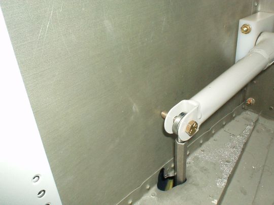
And finally, the hole for the flap pushrod must be cut through the
fuselage. The fuselage side skin actually already comes with a
little guide notch, but I wish it didn't. Suspicion confirmed --
the pre-punched guide notch wasn't exactly in the right place. I
cut the hole progressively, starting with the bottom skin and working
up to the notch in the side skin. What I did was mount the rod
end bearing to the flap and raise it as far as it goes until the rod
end bearing hits the fuselage skin. Mark its outline, and
cut. Repeat until flaps can raise all the way up, with rod end
bearing fitting through the cutout in the skins. Now, with the
flaps up, connect the pushrod to rod end bearing on the flap and to
torque tube arm. The issue here is that the geometry is such
that as the flaps are raised or lowered, the location where the push
rod intersects the fuselage bottom skin moves around a bit.
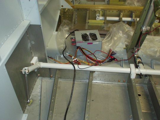
Using the actuator motor (with 12V computer power supply and a
switch), lower the flap carefully until the push rod is about to hit
the bottom skin, then STOP! Mark the location, and trim.
Repeat until the pushrod clears the skin through the full
travel. You end up with sort of a peanut-shaped (and
peanut-sized) hole in the bottom skin.
Note: Van's callout for the flap pushrods is 5/16 inch aluminum tubing
(0.058 wall thickness), drilled and tapped for the 1/4 inch rod end
bearings. This pushrod has been a common point of failure, and I
can see why. Just looking at the tube stock, it seems way too
flimsy for the job. A common solution, and the one I employed,
is to replace these with ones made from 3/8 inch aluminum hex bar. Bought them
ready-made from Avery, $16 and worth every
penny. These feel ten times stronger. Note however that
because their diameter is slightly bigger, the cutout in the fuselage
skin has to be slightly bigger, but no big deal.
 |
| 2010.09.27:
(0.0) Finished with the
fitting the left wing, I called over my trusty helpers and we did a
wing swap. Off came the left, moved the fuselage over about 5
feet to the left, and mounted the right wing. Thanks to Chris
B., John F., and John N. for the help! |
| 2010.10.01:
(0.0) Fit the right fuel
tank support bracket. |
| 2010.10.02:
(0.0) Fabricated and fit
the right fuel tank vent line. |
| 2010.10.29:
(0.0) Finished all
remaining fitting work with the right wing (same as done on left wing,
documented above). Removed the wing and put it back on the
cradle, and rotated the fuselage back to its previous position with
the nose pointing out. This was done with the help of John N.,
John F., and Brandon S. Thanks guys! |
| 2010.11.03:
(0.0) Drilled the holes
in the fuselage sides for the wing wiring harness penetrations that I
marked previously.
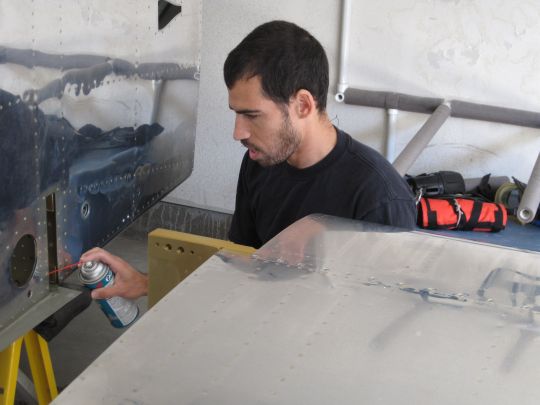
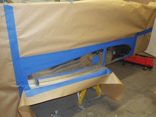
I noticed that there were a few spots on the fuselage at the wing root
area that were starting to develop a bit of filliform corrosion.
I first of all took care of it (abraded off the corrosion, and touched
up with alodine pen). But I also decided to protect the whole
area from corrosion by spraying epoxy primer on the entire wing root
area of the fuselage side that will be enclosed by the wing root
fairing, as well as the adjoining area around the main landing gear
penetrations that will be hidden by the intersection fairings.
My thinking was that the airplane will probably be painted with the
wings on, after it's already flying, so those areas may not get good
paint coverage due to their limited accessibility with the wings and
landing gear attached. I spent a few hours masking... and then
about 15 minutes prepping (cleaning and abrading), and another 5
minutes actually shooting primer.
 |
|
|