|
  

Landing Lights
Running Total Hours:
0.0
 | 2010.06.22:
(0.0) The airframe per
Van's design does not make any specific provisions for the
installation of landing lights [note].
However, several 3rd party kits exist, one of which -- the Duckworks
kit -- has become the de-facto standard, and this is the one I'm
using.
[Note: As of a recent design change, Van's
latest wing tips include provisions for landing lights. However,
I have the older-style wing tips, and in any case I prefer the
Duckworks design for a multitude of reasons.]
The Duckworks design calls for a cut-out in the wing leading edge skin
in the outboard-most wing bay. This is where weakening the wing
box a bit has the least effect (Van's approves of this), and where the
light will cause the least amount of reflection off the prop
disc. A shaped acrylic lens closes the cutout, and an adjustable
mounting bracket for the lamp fixture is mounted inside the wing bay,
right behind the lens. The original Duckworks design used parts
from an automotive driving light (55W H3 halogen bulb and a
rectangular reflector), which was a very elegant and cost-effective
solution. Other versions were later made available, including a
more powerful round aviation-style PAR36 bulb, as well as automotive
HID lamps. The beauty of the Duckworks design is that all these
lamp styles are easily accomodated, and even easily interchangeable /
upgradeable by just replacing the adjustable mounting bracket.
In my case, I'm planning on using LED-based landing lights (either
from AeroLEDs or of my own design), and so I simply purchased
"blank" mounting brackets from Duckworks, without any of
their lamps.
I opted to install two landing lights, one in each wing. This
will give me 1) better illumination for takeoff/landing/taxi
operations, 2) a measure of redundancy in case one light fails in
flight, and 3) the possibility of a wig-wag flasher capability to make
my aircraft more visible in flight. |
| 2010.06.22:
(0.0) So let's get to
it. Currently with the left wing temporarily attached to the
fuselage, this is a convenient time to do the left landing
light. I started by marking the leading edge cutout outline on
the wing. The Duckworks kit comes with a paper template and
dimensions on where to locate it relative to the top skin joint over
the spar and the rivet line of the inboard rib of the outboard
bay. I measured and marked the rectangular outline on the wing
based on the dimensions alone, and then placed the paper template over
it and used it to mark the outline of the rounded corners. I
also took this opportunity to mark the locations of the mounting
screws, using the pre-punched backing strips as a guide over the paper
template. Note that with the dimensions given, about two thirds
or more of the cutout ends up on the bottom of the wing. This
looks suspicious at first, but I verified that that's the correct
position (the light gets aimed down slightly). Definitely a case
for measure twice cut once! And now for the slightly scary part
of cutting the big hole into a perfectly good wing. I started by
drilling a hole near the upper right corner, and then used a milling
bit in a rotary tool (i.e. cheap Dremel knock-off) to do the initial
cut. I kept it about 1/8" from the final outline at this
point. I then worked it toward the outline with a sanding drum
in the air drill, then some touch-ups with files, and finally I
polished it nice and smooth with a scotch brite drum in the air
drill. Came out great! |
| 2010.06.23:
(0.0) Drilled #40 pilot
holes for the 6 screws that secure the lens in place. Used the
marks I made previously to position the pre-punched backing strips,
which I used as a drill guide.
Did the initial trimming of the acrylic lens. |
| 2010.09.02:
(0.0) This entry describes
work from a while back...
Finished fitting the lens and related hardware, although I may still
choose to trim the side edges a bit more to facilitate insertion and
removal when the lamp mounting plate is in place.
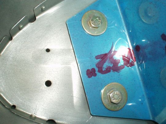
The paper templates provided to locate the bolt holes in the ribs were
printed a bit out of scale, as measured against the hole spacing on
the mounting plate. The holes on the mounting plate flanges are
deliberately cut oversized to allow for adjustment of the light
geometry, so it's somwhat forgiving of the bolt position. But as
it is easy enough, I re-scaled the templates on a xerox machine to get
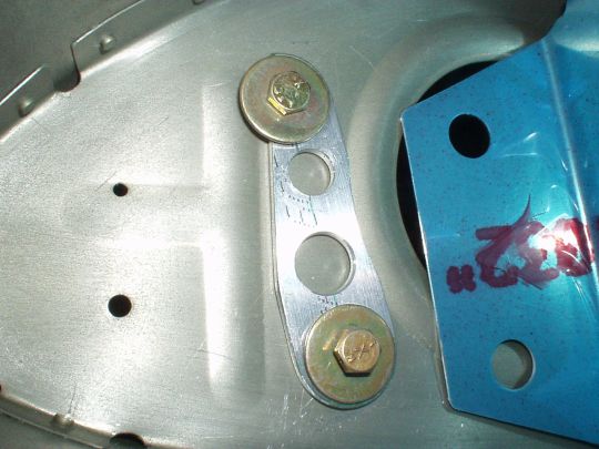
it as close as possible. Another more annoying issue, the
mounting plate is about 1/4 inch too narrow to fit properly between
the ribs. Argh... So I made some 1/8" spacers (one
for each side of the bracket). I cut them such as to prevent
interference with the stiffener beads in the rib, which actually would
have interfered had the mounting plate been the "correct"
width. Everything about this installation is just a little
"off" like that... but at this stage in the project I know
this is par for the course. Easier to just make it work than to
bitch about it.
 |
|
|