|
  

Elevators Construction
Start: 2004.12.21, Completion:
2005.04.07, Hours:
100.0
 | 2004.12.21: (2.0)
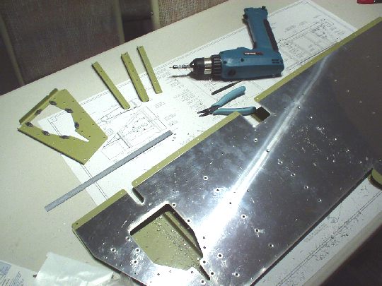
Started making the stiffeners for the right and left elevators.
Much faster method than what I did on the rudder: 1. separate
individual stiffeners using cutting disc in a die grinder, 2. rough
cut (~1/16" from line) stiffeners on the band saw, 3. clean up
the cuts on the bench grinder (scotchbrite wheel). |
| 2004.12.22: (2.0)
Finished grinding down the stiffeners to final shape. |
| 2004.12.23: (3.0)
Edge-finished the stiffeners. |
| 2004.12.25: (1.5)
Final-drilled the stiffeners to the right elevator skin. Used a
reamer instead of a regular jobber bit, which produced cleaner holes
with less burr. Deburred the holes. |
| 2004.12.26: (2.5)
Edge-finished the right elevator skin. Dimpled the
stiffener-to-skin rivet holes on the skin and the stiffeners. |
| 2004.12.27: (1.5)
Final-drilled the stiffeners and trim reinforcement plate to the left
elevator skin. |
| 2005.01.08: (1.0)
Edge-finishing the left elevator skin... |
| 2005.01.09: (1.0)
Done edge-finishing the left elevator skin. |
| 2005.01.10: (1.0)
Dimpled the left elevator skin. |
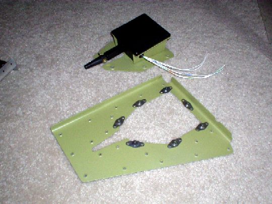
| 2005.01.16: (2.0)
Fitted the parts associated with the trim servo installation.
The servo cover plate does not come with pre-punched holes for the
servo support Z-brackets, so locating them is the first order of
business. The plans provide one dimension callout for the
distance between the edge of the cover plate and the edge of one of
the Z-brackets, and that's all. Seems to me that referencing the
installation to this dimension is not the best way to go about it, as
it is only indirectly related to the truly critical dimensions and
introduces several unnecessary sources of error. It's critical
that the servo be positioned such that the servo shaft (and jackscrew)
be properly aligned with their respective exit cutouts in the
elevator. So I started by locating the servo shaft centerline on
the elevator components to serve as the master reference. Then
located the servo housing centerline and the Z-bracket rivet lines
based on the shaft centerline and dimensions of the servo and
Z-brackets. In the longitudinal axis I located the servo as far
forward (toward the spar) as possible without modifying the
Z-brackets, as limited by their contact with the trim reinforcement
plate. This dimension is not explicitly called out in the plans
at all. Locating as forward as possible minimizes its effect on
elevator balance, and therefore the necessary counterbalance
mass. As noted in the plans, a small amount of trimming is
necessary to the trim cover plate and reinforcement plate to prevent
interference with the clevis pin when the servo shaft is in its
extreme extended position. |
| 2005.01.20: (1.0)
Finished preparing (edge-finishing, c-sinking, dimpling) the parts
associated with the trim servo installation. Clearance is very
tight between the servo and the aft rivet connecting each of
Z-brackets to the trim plate, likely to interfere when dimpled for
AN426AD3 rivets. So I decided to substitute a NAS1097AD3 rivet
for the AN426AD3 and machine countersink the hole instead of
dimpling. With no dimple, clearance should be ok. The
NAS1097 rivet has a smaller head and therefore will not leave a
knife-edged hole after countersinking. Although it has reduced
tensile strength, I believe it is preferable in this location where it
should experience primarily a shear load. All
other rivets are as called out on the plans. |
| 2005.01.29: (1.0)
Edge-finished the hinge reinforcement plates and one of the
spars. Then noticed that the outboard hinge reinforcement plates
don't fit the spar. Looks like Van's sent me the wrong
part. They look suspiciously like one of the hinge reinforcement
plates on the rudder. |
| 2005.01.30: (3.5)
Applied corrosion protection to the right elevator stiffeners and left
elevator trim reinforcement plate. |
| 2005.01.31: (0.5)
Installed nut plates to the trim reinforcement plate. |
| 2005.02.01: (2.5)
Applied corrosion protection to the right elevator skin. |
| 2005.02.04: (1.0)
Riveted the stiffeners to the right elevator skin. |
| 2005.02.09: (3.5)
Applied corrosion protection to the left elevator stiffeners and trim
servo plate and brackets. |
| 2005.02.10: (0.5)
Riveted the trim servo assembly. Even with the countersunk
NAS1097 rivets in the aft position, clearance indeed turned out to be
an issue (see 2005.01.20 entry). I had to over-squeeze these
rivets somewhat to fit the servo, and I may still decide to shim it up
a little to prevent possible rubbing on vibration.
 |
| 2005.02.12: (1.0)
Edge-finished the correct hinge reinforcement plates just received
from Van's. Started edge finishing the ribs. |
| 2005.02.13: (1.5)
Edge-finishing the ribs... |
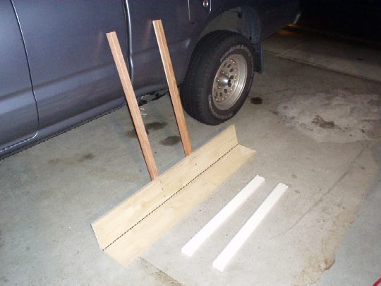
| 2005.02.19: (1.0)
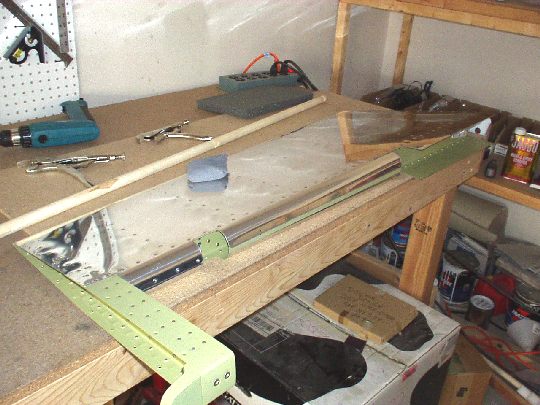
Built a bending brake for the elevator trailing edges using some
1"x6" poplar and a piano hinge from Home Depot.
 |
| 2005.02.20: (4.0)
Bent the right elevator trailing edge. Started drilling the
right elevator counterbalance arm components. Today I had help
from my brother (and future homebuilder) Omri, and my sister (and
future airsick passenger) Eynav.
 |
| 2005.02.21: (1.0)
Drilled the lead counterweight to the structure. Drilling lead (Pb)
can be a bit tricky as it has a strong tendency to bind. I
destroyed one drill bit discovering this tendency, but thankfully I
managed to stop the drill press before it could toss the counterweight
across the room. After that I did ok, using WD-40 for
lubrication/cooling and going in very small increments, backing out
every few millimeters and clearing the lead out of the drill
bit. I also started with a #40 drill and incrementally enlarged
the hole to #12 with about five drill sizes in-between. A little
time-consuming, but the end result was excellent. Countersunk
the weight, dimpled the counterbalance skin, did a fit check. |
| 2005.02.24: (2.0)
Drilled the right elevator skin to the understructure.
Disassembled and deburred the holes. |
| 2005.02.25: (1.0)
Dimpled the right elevator components. |
| 2005.02.28: (1.0)
Quickly reassembled the right elevator and match drilled the
fiberglass tip (should have done this before, when drilling everything
else).
Removed material from the lead counterweight as shown on the
plans. Rough-cut using the band saw, then filed down. |
| 2005.03.01 (3.5)
Applied corrosion protection to the remaining right elevator skeleton
components. |
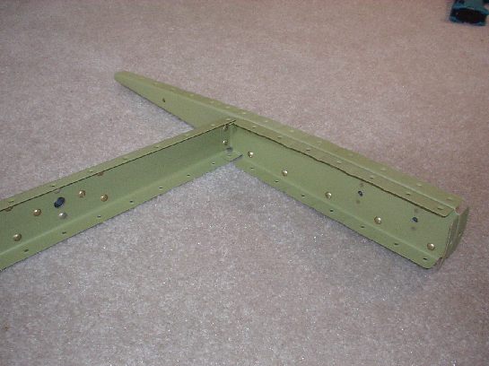
| 2005.03.02: (1.0)
Started riveting up the right elevator skeleton. Found that a
longeron yoke will be needed to rivet the counterbalance ribs to each
other.
The control horn weldments are 4130 chromoly steel and come
powder coated, but the powder coat doesn't cover the inside of the
torque tube, which is open on one side. To help protect from
corrosion I decided to coat the inside with Rustoleum primer and
paint. Did so by pouring it in, sloshing it around, then drain
the excess and blow it out with compressed air. |
| 2005.03.03: (1.0)
Ordered a longeron yoke from Cleaveland Tools ($135, ouch!!!), and for
today I borrowed one from fellow builder Greg Larson. Finished
riveting the right elevator skeleton, except for the control horn,
which is still drying.
The current design of the counterbalance arm has the lead mass mounted
in such a way that it is not removable, and only minimally accessible
for removing material via drilling. The fiberglass fairing also
gets epoxied to the lead weight, making it more or less a permanent
installation. Once in place, there is no practical way to add
mass if it becomes necessary. So I decided to install two 10-32
plate nuts on the counterbalance rib, where additional mass could be
attached if necessary.
 |
| 2005.03.04: (1.5)
Riveted on the right elevator control horn and started riveting on the
skin.
RTV folklore: there's a common practice of putting a glob of RTV
silicone between each opposing pair of stiffeners near the trailing
edge to "tie them together" thereby minimizing vibration and
preventing cracks. This measure struck me as dubious in its
necessity and effectiveness, so I dug a little further into its
origins. I found that this dates back to a couple articles in
the 12/89 and 12/91 issues of the RV-ator in response to some builders
of early RV's experienced cracking in these areas. Since that
time however, the stiffeners have been redesigned to extend closer to
the trailing edge, and the skins themselves have been thickened from
0.016" to 0.020", both of which should make the trailing
edge much stiffer than on the early RV's. I did not want to add
any unnecessary weight that far aft, and especially at the trailing
edge of the elevators (not just the weight of the RTV itself, but also
of the added counterbalance weight), so I decided to consult
Van's. I spoke with Tom Greene, who concurred that the RTV is
most likely unnecessary with the thicker skin, and told me that
cracking was mainly a problem on early RV's with larger than
recommended engines. He also shared my doubts about the ability
of RTV to permanently bond the stiffeners together. So, I
decided to omit the RTV from my elevators. Will they
crack? Time will tell. |
| 2005.03.05: (0.5)
Finished closing the right elevator. |
| 2005.03.06: (2.0)
Applied corrosion protection to the left elevator skin. |
| 2005.03.07: (1.0)
Riveted the stiffeners to the left elevator skin. |
| 2005.03.09: (1.0)
Started bending the left elevator trailing edge with Vay's help.
I thought the left elevator would be easier than the right because it
has less trailing edge (due to the trim tab cutout). But in fact
that just makes it more awkward and difficult to hold in position in
the bending brake. Still, with some strategy and a little yoga
it's going ok. Just a few more degrees to go. |
| 2005.03.10: (0.5)
Finished bending the left elevator trailing edge. |
| 2005.03.12: (2.0)
Preparing the left elevator skeletal pieces. |
| 2005.03.13: (2.0)
Drilling the left elevator skeleton. |
| 2005.03.14: (2.0)
Prepared the left elevator trim spar. Beveled the counterbalance
skin where the main skin transitions off. Drilled the lead
weight to the counterbalance arm components. |
| 2005.03.15: (2.0)
Today disaster struck... I started to cleco up the left elevator
for final drilling only to discover a serious problem. The holes
in the skins and the holes in the skeleton were just not lining up
right, getting worse toward the tip. Forcing the holes to line
up would cause a substantial "hook" at the trailing
edge. After examining the geometry and taking a few quick
measurements it became clear that the trailing edge bend in the skin
was off its proper axis. Worst at the tip end, the distance from
the trailing edge to the spar was different on the top and bottom by
about 1/16". I'm not sure how this happened, whether it
happened during my final bending or whether the initial bend was off
out of the box. But in any case, the skin will have to be
replaced. This sucks!
I spent the rest of the evening drilling out all hundred or so rivets
attaching the stiffeners to the skin. My one consolation is that
this operation went well and the stiffeners will be usable with a new
skin.
 |
| 2005.03.16: (3.0)
Ordered a new left elevator skin from Van's. That's $60 and
about 10 hours of work down the drain, but sometimes that's just how
it goes. Back to work. Countersunk the lead weight.
Countersunk plate nut mounting holes in the counterbalance rib (my
modification, same as right elevator). Edge-finished the trim
tab components and drilled the trim tab horn to the skin and spar. |
| 2005.03.17: (3.0)
Rolled the leading edge of the right elevator. This actually
seemed to go easier than on the rudder, despite (or maybe because) of
the thicker elevator skin. It took more force to roll a given
amount, but seemed to have less spring back.
 |
| 2005.03.18: (0.5)
I decided to make a minor modification to the trim servo
installation. I didn't like the idea of routing the wiring
through the same hole in the elevator spar that the jackscrew moves
through (the wiring could flop around, catch, rub, etc.) as shown on
the plans. So I drilled a separate 3/8" hole in the elevator spar
just for the wiring. The location of this hole is closer inboard,
right in the center of the lightening hole of the control horn
weldment. Although this is a very minor deviation from the
plans, it is in a structurally critical area, so I cleared it with
Van's for good measure. |
| 2005.03.19: (4.0)
Received my replacement left elevator skin from Van's. I
edge-finished it without use of the die grinder, as it was late at
night, which took about twice as long. Next time I'll wait until
morning and make all the noise I want. |
| 2005.03.20: (1.5)
Did a quick fit check with the stiffeners and the new skin. Then
reamed, deburred, and dimpled the holes in the skin for attaching the
stiffeners. |
| 2005.03.21: (1.5)
Alodined the new left elevator skin, spar doublers, and trim tab skin. |
| 2005.03.22: (2.0)
Shot AKZO on the new left elevator skin, spar doublers, counterweight,
and trim tab skin. Several hours later ... bent the trailing
edge of the trim tab. |
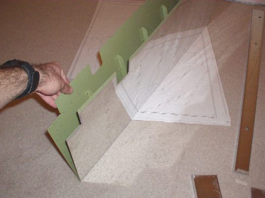
| 2005.03.23: (2.0)
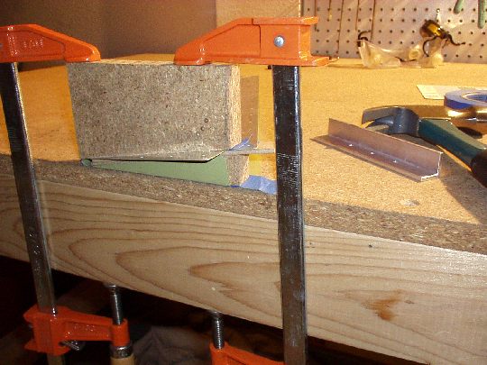
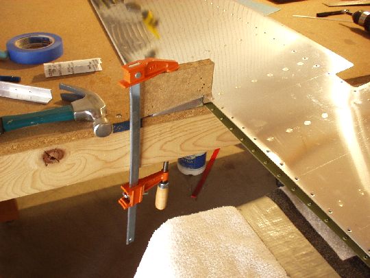
Bending the ends of the trim tab: Made a bending block wedge
(and its complement) from a piece of thick particle board left over
from the material I used for the top of my workbench. On the
wedge piece, which actually functions as the bending block, I radiused
the edges using just a file, sandpaper, and eyeball. I made it
just a simple wedge without the interlocking feature shown in Van's
manual, since that design would only work for the trim tab and not the
elevator. I then made the first bend on the lower inboard end of
the trim tab. I used blue masking tape on the trim tab to both
protect it from scratches and provide some friction to keep things
from moving around. With that and clamping the whole stack to
the workbench, nothing was going anywhere. First bend completed
to about 90 degrees. A tad more is needed due to the geometry of
the trim tab, but I'll do that tomorrow.
Riveted the stiffeners to the new left elevator skin. Later Vay
came over and we bent the left elevator trailing edge, again.
Did a quick fit check with the tip rib, and this time the holes line
up. Whew! |
| 2005.03.24: (6.0)
Match-drilled, deburred, and dimpled the left elevator. |
| 2005.03.25: (1.5)
Finished bending the ends of the trim tab. Match-drilled the
trim tab skin to the spar, hinge, and control horn components. |
| 2005.03.29: (0.5)
Bent the left elevator tabs that close off the trim tab cutout.
Nothing to it.
 |
| 2005.03.30: (1.5)
Alodined the remaining left elevator and trim tab components. |
| 2005.03.31: (3.0)
Shot AKZO on the remaining left elevator and trim tab components.
Later in the day, riveted the bottom of the trim tab and riveted the
left elevator skeleton. |
| 2005.04.03: (2.5)
Riveted the left elevator skin to the skeleton, except for the where
the trim tab hinge attaches.
On the left elevator I decided to follow tradition and put a glob of
tank sealant between each pair of opposing stiffeners near the
trailing edge. I stand by my reasons for not doing this on the
right elevator (time will tell), but decided to do it on the left to
alleviate my paranoia about using the stiffeners that had been drilled
out from the original skin following the March 15 disaster.
Also, on the left elevator there are only four pairs of stiffeners
that reach the trailing edge (because of the trim tab cutout), so the
weight penalty is smaller. Anyhow... I chose to use tank
sealant rather than RTV because 1. I believe it will form a stronger
bond that will last longer, 2. I already had a tube of it laying
around, and 3. I wanted to try it, having never used it before.
The stuff I used was FlameMaster ChemSeal 3204-B2 from Aircraft
Spruce. This conforms to MIL-S-8802F Type II (a.k.a. AMS-8802),
and is equivalent to PPG ProSeal brand sold by Van's. As
everyone says, this stuff is very sticky and can get messy. I
did go through several sets of latex gloves and popsicle sticks, but
it really wasn't bad at all. When applying it I was careful to
get it to the ends of the stiffeners but no further, so as to not
obstruct the natural drainage channel at the trailing edge. I
also applied leftover tank sealant to a few test patches of different
materials so I know how well it works for future reference. It
performed well with every surface I tried including clean but
untreated alclad, AKZO epoxy primer (like the inside of my elevators),
stainless steel, wood, PVC, and even delrin. Good stuff! |
| 2005.04.04: (1.0)
Fitted and closed the trim tab. The fit to the elevator was very
good at the outboard gap and trailing edge, but the inboard edge of
the trim tab protruded about 3/16" past the inboard edge of the
elevator. I called Van's to make sure this is not a problem. |
| 2005.04.05: (0.5)
Shot AKZO on the forward (elevator) half of the trim tab hinge. |
| 2005.04.06: (1.0)
Finished riveting the trim tab cutout area in the left elevator. |
| 2005.04.07: (1.5)
Rolled the leading edges of the left elevator. Added a few extra
rivets toward the outboard end to help with the spring back.
Primary construction of the elevators is complete. |
| 2006.12.18: (0.0)
See "Attaching the Empennage"
for fitting elevators to the horizontal stabilizer. |
|
|