|
  

Empennage Fiberglass Tips & Fairings
Running Total Hours:
0.0
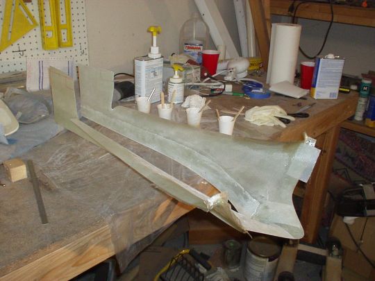
 | 2007.04.17:
(10.0) Trimmed and
fitted the rudder bottom fairing. The fairing as it arrives from
Van's is composed of two molded halves that have already been
joined. Unfortunately, the weren't joined quite symmetrically,
and had some definite twist. It was close enough to be usable,
but just wasn't pretty if you sight it down very closely. Having
resigned to pick my battles with Van's, I decided to use it anyway and
make the best of it by trimming such as to balance the twist fore and
aft as much as possible. I also found that the forward end fit
better inside the flanges of the rudder's spar than outside. So
be it.

The rudder bottom fairing attaches to the rudder from the
outside. Or in other words, the aluminum flanges of the rudder
go behind the fiberglass. I decided to fasten the fairing to the
rudder using platenuts and MS24693C2? #6 stainless steel sountersunk
screws. To better protect the fiberglass from the head of the
screw, I'm also using countersunk finishing washers to spread the
load. I will likely use the same method to fasten other fairings
that attach from the outside.

It seems that MS24693C screws are not so easy to find in certain
sizes. But between Aircraft Spruce and McMaster-Carr I was able
to get a good assortment. The stainless steel countersunk
finishing washers also came from Aircraft Spruce (Spruce p/n 04-00397,
Mfg ??? p/n A3236-SS-012). |
| 2009.03.17:
(0.0) Working on the elevator
tips. I had already drilled them way back when I built the
elevators, but now there is still trimming to be done, and ultimately
some kind of closure around the front where the lead weights are
located. For now, I just cut the clearances around the front so
there's no interference with the lead weights. And I bonded in
some 0.020" aluminum backing strips to spread the pressure of the
pop rivets that will hold the tips in place. |
| 2009.04.06:
(0.0) Working on the right
elevator tip. I filed down the lead counterweight around the
sides to remove interference with the fairing, and around the front to
match the curvature of the aluminum inboard of it, plus a few mils
deeper to leave room for fiberglass. I laid up fiberglass (one
ply of RA7781) all around the part of the lead counterweight that
resides inside the fairing. I figured that doing this would give
me the best possible adhesion over the largest possible surface area
of the lead, and then provide a better bonding surface (fiberglass
rather than lead) for the final installation of the fairing.

[these photos actually show the left elevator, which I did later]
I
also laid up another layer of glass on the inside of the fairing for
about 2" from the forward end to reinforce it (these molded parts
from Van's are pretty crappy, and this one had massive voids and
cracks in that area, which I fixed as well as I could). With
this added glass there was still a millimeter or two of clearance
between the fairing and the lead weight. I installed the
fairing, using flox to fill that clearance.

I also used flox to
bond the fairing along its length to supplement the pop-rivets and
fill the seam. Since the lead counterweight design forced me to
bond the fairing in that area, making it a "permanent"
installation, I figured I may as well bond the rest of it too and make
it as strong as possible. After this all cures, I'll sand down
the forward end to a nice contour, and add a ply of glass to seal the
deal.
Side note: For my next RV (just kidding!) I would consider another
approach, and make the elevator tips removeable. Van's sure
didn't make that easy with the molded counterweight design, but by
trimming back the counterweight even further, and capping the fairing
around the front, it could be done. That would make it possible
to adjust the counterweight without drilling holes into it from the
outside ("sub-optimal", to put it nicely), and would also
eliminate the need to bond composites to metal (also
"sub-optimal").
Working on the left elevator tip, same technique, just a few steps
behind. And I also started fitting the HS tips. |
| 2009.04.16:
(0.0) Elevator tips are now
bonded closed, but more shaping and possibly some glassing will be
required at the forward ends.
Started working on the HS tips. Matched drilled the tips to the
HS, and trimmed them to achieve the minimum 1/8" gap from the
elevator counterweights. Bonded 0.020" aluminum strips on
the inside to reinforce the rivet line. I decided to cap the aft
end of the HS tips, and my technique of choice was to form an end rib
and then bond it in place. I fabricated the end rib by making a
balsa core (2 plies of 1/8" balsa bonded together with their
grains at 90° to each other), and then laying up fiberglass to
encapsulate them all around. The fiberglass along the edges then
provides a good surface for bonding into the tip using flox.
 |
| 2009.05.28:
(0.0) I permanently installed
the HS tips using CS4-4 pop rivets and epoxy/flox.
I fitted the top rudder tip. This one was a bit of a challenge
because it was molded complete at the factory, including the forward
end cap, but was about 3/16" too short for a good fit. Argh
@#%$!!! I know this is a common problem because I've seen
completed RV's where the builder just attached the tip with this
grossly poor fit (very noticeable!). Anyway, I decided to fix
this by building up material to extend the forward end cap. This
approach will add just a bit of extra weight, but it's actually in the
ideal location to aid in counterbalancing the rudder, so I'll take
it. I did this by prepping the surface of the forward end cap,
taping a "dam" of 4 mil plastic sheeting to extend the
contour of the fairing as an ad-hoc female mold, and then pouring in
flox about 1/4" deep. I should elaborate just a bit further
on the flox. I actually poured it in in several stages, starting
with neat epoxy and moving gradually to increasingly thick
mixtures. I did this to ensure that I didn't get any voids
around the sides where a viscous mixture would have a hard time
penetrating.

After it cured, I then shaped the flox using abrasives and files,
first the bottom part to fit into the rudder counterbalance arm, and
then the top part to match the exterior contours.
Note also that I elected to make the rudder top tip removable using
screws and nutplates rather than to permanently install it. I
made this decision early on when I built the rudder, the reason being
to provide access to add counterbalance weight if necessary using a
couple of extra nutplates that I installed on the top of the
counterbalance arm. Not sure if this will be necessary or
not. I'm told that rudder doesn't need to be quite neutrally
balanced. But anyway, the provision is there.
Finally, I fitted the VS tip using the same methods I used for the HS
tips.
All that remains now is a bit of sanding to shape the forward end caps
of the elevators and rudder, and surface finishing, i.e. fill, sand,
fill, sand... on all the emp tips. I'll put that off for
now. I need a break from composites work. |
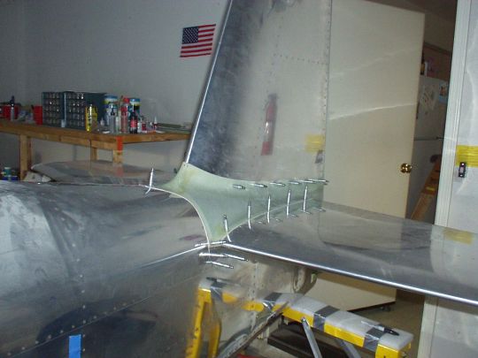
| 2010.11.14:
(0.0) Fitting the empennage
fairing... Like most of the fiberglass components in the kit, it
fits just well enough to make me not want to throw it away and start
from scratch, but poorly enough that it'll take a week or two to
massage it into a good fit. I'm now a few days into that
drudgery, but it's starting to shape up.
I'm also making some mods in the attachment of the bottom gap
fairing. In the plans, this aluminum strip is attached to the
fuselage using #6 screws (into tapped holes in the longeron) and a
rubber channel closes the gap between the top of the strip and the
bottom skin of the HS. Several details of this attachment are
clunky at best. Given that, and the fact that there is no good
reason for the bottom gap fairing to be removable, I've decided to
simply rivet it to the fuselage, and use proseal to fillet the
intersection between the top of the gap strip and the bottom of the
HS. Not done yet, but that's the plan.
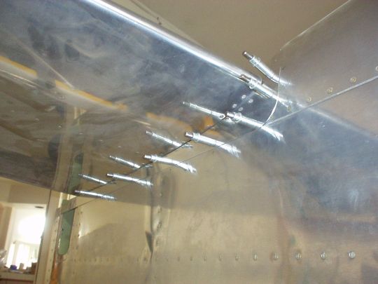
I just noticed that I hadn't taken any pictures of the installed HS
and VS tips (done last year), so here are some pics:

 |
|
|