|
  

Rudder Construction
Start: 2004.08.16, Completion:
2004.12.29, Hours: 60.0
 | 2004.08.16: (0.5)
Separated the rudder stiffener stock into individual stiffeners using a Dremel cutting
disk mounted in the air drill. |
| 2004.08.18: (1.5)
Rough-cut the
tapered (aft) ends of the stiffener flanges on the band saw. Started filing down the
long cuts.
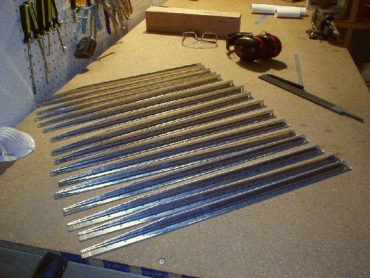 |
| 2004.08.21: (2.0)
Finished shaping the tapered ends of the stiffeners using a vixen file
followed by the bench grinder. |
| 2004.08.23: (2.5)
Cutting/shaping the forward (non-tapered) ends of the
stiffeners. |
| 2004.09.11: (3.0)
Finished fabricating and deburring the stiffeners. |
| 2004.09.18: (3.0)
Match-drilled the stiffeners to the skins, deburred all the
holes. Used 1/4" particle board under the skins and drilled
right into it as suggested in the manual. Worked great.
 |
| 2004.09.20: (1.0)
Fabricated the control horn shim. Shaped the top edge of the
control horn to fit the bottom rib. |
| 2004.09.22: (1.0)
Finished fitting and match drilling the control horn assembly with the
bottom rib, front spar, etc. |
| 2004.09.??: (2.0)
Prepared the spar and ribs (edge finishing, fluting, etc.). |
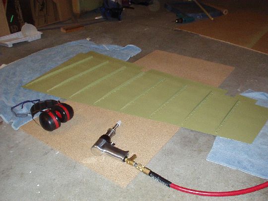
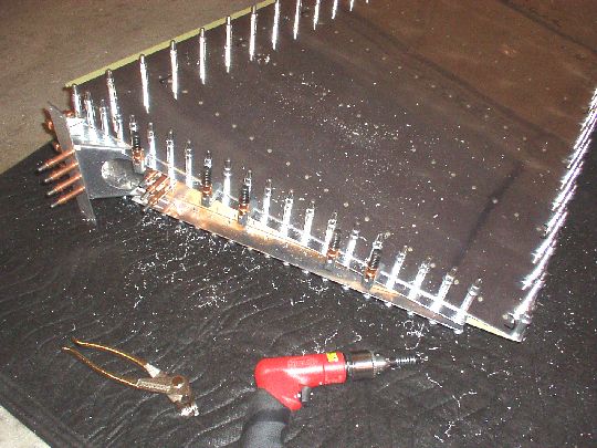
| 2004.10.17: (2.0)
Edge-finished the right side skin. Dimpled the right side skin
and stiffeners. |
| 2004.10.29: (1.5)
Edge-finished the left side skin. My new favorite way of
finishing long edges on skins is as follows:
1. File down the edge to remove large burrs and other marks from the
cutting press. A 6" bastard cut mill file works well.
2. One or two passes with the file at 45 deg on both sides to break
the edges.
3. One or two passes with a 1" fine scotchbrite wheel in a right
angle die grinder to remove filing marks. After this step the
edge is rounded and smooth to the touch.
4. A quick pass with maroon scotchbrite pad for good measure. |
| 2004.10.30: (1.0)
Dimpled the left side skin
and stiffeners. |
| 2004.12.04: (2.0)
More deburring and dimpling...
Just got some more dimpling dies and countersink bits from
Cleveland. One set for #10 screws (for the counterweight
attachment) and one set for 1/8" 120 degree countersunk blind
rivets, like CS4-4. |
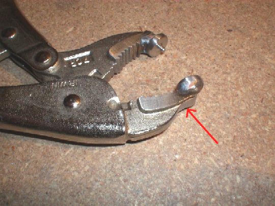
| 2004.12.05: (1.0)
And some more... Modified my Avery vice grip dimpler on the
bench grinder to help it get into even tighter places, like the last
few holes in the ribs near the trailing edge.
 |
| 2004.12.06: (1.0)
First not-so-successful attempts at countersinking the trailing edge
wedge. This task is slightly complicated for a couple of
reasons:
1. The wedge is very thin, so the holes are enlarged once countersunk
from both sides. This means half way through countersinking the
second side, you no longer have a good guide hole and the bit tends to
chatter.
2. Since the wedge is a wedge (redundantly redundant) the holes aren't quite
perpendicular to the surfaces, also affecting the guide pin of the
countersink bit.
First attempt using a hand drill holding the wedge flat against the
countersink cage had limited success. For a second attempt I
used some thin plywood and clecos to support the wedge with its upper
surface perpendicular the countersink cage in drill press. That
was better, but there was still a tendency to chatter on the second
side. Will try adding rigid back support or clamping to the
table to minimize motion. |
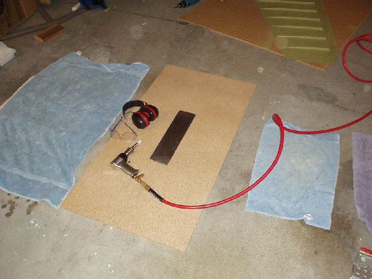
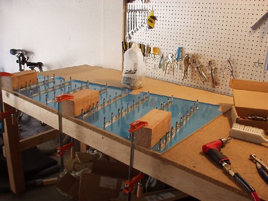
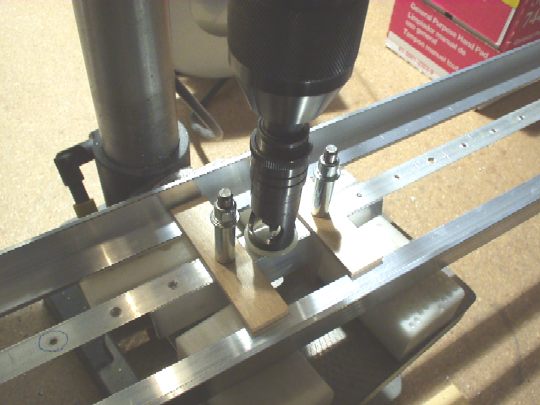
| 2004.12.07: (1.0)
Took a trip to a local metal supplier and bought some alum
angle. Cut a piece to act as backing and match-drilled it for
three rivet holes on the wedge. Note that because this is a
backing piece the holes should end up at an angle to it, so that
they're perpendicular to the opposite surface of the wedge. Used
larger pieces of the angle to act as rails to support the wedge on the
drill press table. A picture is worth a thousand words, so here
it is. This worked very well.
 |
| 2004.12.15: (1.5)
Prepped and alodined the rudder skeleton parts. |
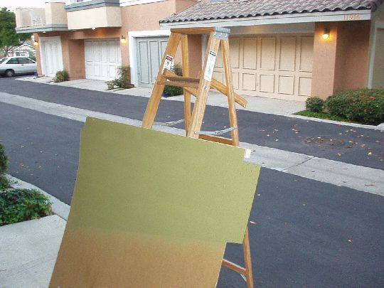
| 2004.12.16: (1.5)
Shot AKZO on the rudder skeleton parts. |
| 2004.12.18: (1.0)
Started riveting the skeleton. After driving a few rivets on the
counterbalance arm, I decided that a squeezer yoke with a 4"
throat will be a better alternative. Ordered one from Cleaveland. |
| 2004.12.24: (1.5)
With my new 4" yoke that just arrive, I easily squeezing the
remaining rivets on the counterbalance skin. Now riveting the
skins to the skeleton. |
| 2004.12.27: (2.5)
A long awaited order from Van's just arrived -- an assortment of
NAS1097AD3 rivets, which are like AN426AD3 but with smaller
heads. Used these to attach two 10-32 nutplates to the top rib,
which will be used to secure additional counterbalance mass if
needed. Finished riveting the skins to the skeleton.
Started riveting the dreaded trailing edge. There's been much
discussion on the message boards lately about different techniques for
doing this. I decided to go with a method of my own. I
laid the rudder down flat on its left side, with the fully clecoed
trailing edge hanging off the edge of the workbench (control horn
hanging off the edge as well). Then one by one I replaced a
cleco with a rivet, inserted from the top (i.e. manufactured head on
right side), squeezed far enough to get a good grip but nowhere near
flush with the skin. Note that all the squeezing at this point
is perpendicular to the plane of the manufactured head, so it's
crucial that the die does not come in contact with the bottom (i.e.
left) skin. The rivet sequence I used was basically starting
from the extreme edges, then half way between, then split the halves
into quarters, etc. for the "even" rivets. Then the
same sequence again for the "odd" rivets. Every few
rivets I checked the trailing edge for straightness and made slight
adjustments as needed. The idea is that the trailing edge starts
out straight and fairly rigid by virtue of all the clecos. Then
it gradually becomes more rigid, and should be vigilantly kept
straight, as clecos are replaced with rivets. At this point, all
rivets are in an partially set. Next, they'll need to be fully
driven by back-riveting. |
| 2004.12.28: (1.5)
Finished the trailing edge by back-riveting. The result is not
perfect, but pretty good. The trailing edge has no bow in one
direction or the other, and is straight to well within the 0.1"
tolerance recommended in the construction manual. The flush shop
heads, which are all on the left side of the rudder, actually look ok.
 |
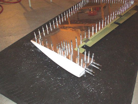
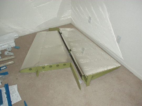
| 2004.12.29: (3.0)
Did the rolled leading edge to finish the rudder. I thought this
step would be easy, but it actually took a lot work to persuade the
leading edge into proper form. Because the leading edge profile
tapers along the rudder's span, the curvature is more parallel to the
spar than it is to the leading edge lap joint. So the
broomstick/pipe method (dowels of various diameters in my case)
described in the manual actually has to be modified somewhat, to tape
the dowel at an angle to the edge of the skin that will form the lap
joint. Then some freehand coaxing to finish the job. A job
like this is never perfect, but I think it came out pretty good.
 |
|
|