|
  

Empennage Attachment / Rigging
Running Total Hours:
0.0
 | 2006.05.02:
(1.0) On the QuickBuild
fuselage, the aft bulkhead comes attached using just a few temporary
pop rivets so that the tail cone could be completed for a tri-gear or taildragger
configuration. I removed the aft bulkhead and adjusted the
flanges for a better fit (it came with all flanges perpendicular to
the web, should fit the conical and tapering skins). |
| 2006.05.04:
(0.5) Greg Larson came over
to help me buck a couple of missing rivets inside the tail cone, at
the bottom of the F-711C bars attachment to the F-711 bulkhead.
They leave these open in the QB so that the non-'A' builders can
attach their misplaced nose wheels. |
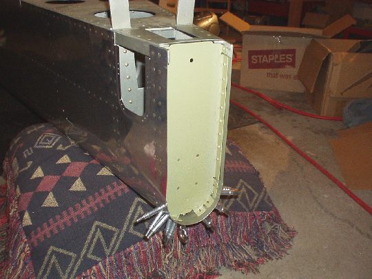
| 2006.05.19:
(1.5) Fabricated the tie
down block and fitted it to the aft bulkhead. |
| 2006.06.30:
(0.5) Alodined the aft tie
down block. Prepped the aft bulkhead for primer (it came primed
in the QB kit, but not very well). |
| 2006.07.01:
(1.0) Sprayed AKZO primer
on the aft bulkhead and tie down block. |
| 2006.07.02:
(2.0) Riveted the tie down
block to the aft bulkhead. Drilled a clearance hole in the aft
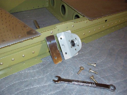
skin for the tie down eye bolt (see note below). Started
riveting the aft bulkhead to the fuselage.
Note: the manual says to drill the tie down clearance hole to
5/8". But the diameter of the shoulder of the tie down rings from
Van's is even bigger. So a 5/8" hole would be much bigger
than needed to clear the 3/8" threaded part, but the shoulder
would still bottom out against the skin rather than the extruded
block. As there is a gap between the skin and the extruded
block, this would tend to bend the skin inward. Not good.
The same situation exists in the wings. And as the wings were
delivered in the QB kit, the clearance holes in the skin are just big
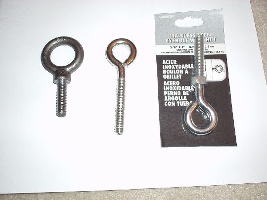
enough to clear the 3/8" threads. I decided to replace the
tie down rings from Van's with something that doesn't have that
shoulder, and could get through an (approx) 3/8" hole and then
bottom out against the block at the end of the threads. A quick
trip to Home Depot yielded the perfect solution. 3/8" x
4" stainless steel eye bolts, rated for a safe working load of
350lb. I'll have to shorten them by about an inch to the ideal
length, but that's no problem. The eye bolts are manufactured by
The LeHigh Group,
product #7134, UPC code 071514002385. At Home Depot they were
located near the ropes and chains, NOT near all the bolts and general
hardware. They were $1.99 each (Van's
tie down rings are $4.25 each).
Pictured: Van's tie down rings on the left, Home Depot on the right
and center.
 |
| 2006.09.17:
(0.5) Now with the fuse
off the ground, I can finish riveting the F-712 bulkhead to close out
the tail cone. Squeezed the ones on the aft flange. Will
need some help to drive/buck the rivets on the forward flange. |
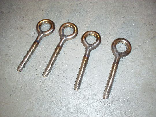
| 2006.10.??:
(0.0) My neighbor Buzz,
who's a professional welder, was kind enough to weld the eye loops on
my Home Depot tie down rings. He used a TIG torch, and it came
out great!
 |
| 2006.11.20:
(1.0) Finished closing
out the F-712 bulkhead with Garnet on the gun and me on the bucking
bar. These were not a great fit, and for a couple we had to
enlarge the hole and use a NAS1097, or "oops" rivet. |
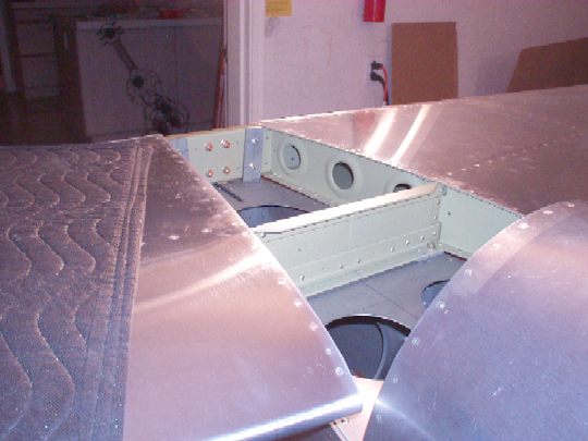
| 2006.12.18:
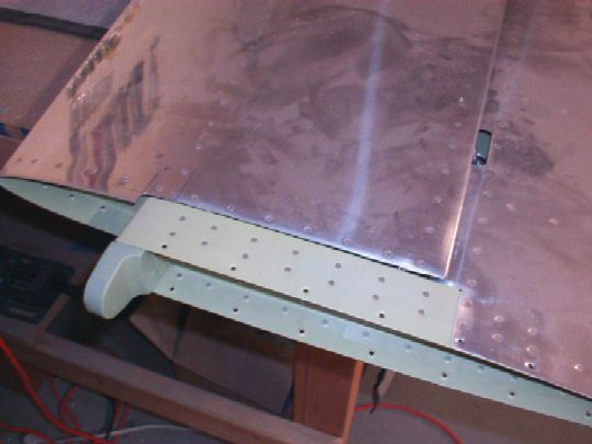
(4.0) Fitting the
elevators to the horizontal stabilizer. Made a couple of
"gauges" from some scrap aluminum to help set the depth of
the rod end bearings precisely to 13/16". Trimmed the HS
skins at the outboard edges to remove interference with the elevator
counterbalance arms. This required extending the clearance area
forward by about 1-1/16", providing the specified 1/8"
clearance.
(Photo below is after rough cut and fit check, before making it
"nice". And the apparent "jaggies" are just
artifacts of rescaling the photo.)
 |
| 2006.12.19:
(2.5) Noticed that the
center elevator bearing assembly wasn't perfectly perpendicular to the
HS rear spar web. Removed it and found that the flange on the
right side was a little off from square, and was also slightly offset
in depth from the left side flange. When bolted to the rear spar
of the HS, the bolts pull it in flat to the spar, which therefore
causes the assembly to lean slightly to the right. I fixed this
by adding a 0.010" stainless steel shim under the right side
flange.
As noted in the manual and plans, the bottom flange of the HS rear
spar channel interferes with the elevator control horns, limiting
elevator down deflection to about 15º. The elevator control
limit should be between 20º and 25º down deflection (builder's
manual, section 15), and should be limited by the down elevator stop
(F-711E), not the rear spar flange. And so the bottom flange of
the HS rear spar channel has to be trimmed back to provide additional
clearance. I cut a notch just over 2" wide (sufficient to
clear the outsides of the horns), and about 11/32" deep (target
depth determined using the "eyeball" method). I
measured after making the notch and found that this allows for
approximately 30º of down deflection, so it'll have 5º to 10º
margin past the stop. Perfect!
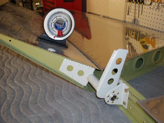
Also measured the max up deflection, which came out to about 40º,
limited by the elevator hitting the aft edge of the HS skins.
The final max up deflection required is 25º to 30º, limited by the
up elevator stop (F-???), so all is good. |
| 2006.12.22:
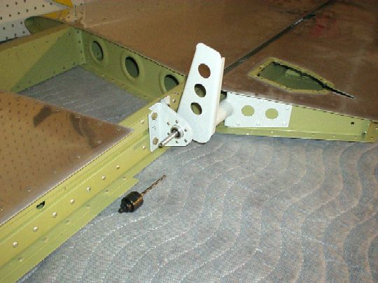
(3.0) Drilled the
elevator horns for the center bearing. To do this I got a piece
of 1/4" aluminum tubing from Marshall's, which had an inner
diameter just about right for a #27 drill bit. I actually had to
reduce the tube's outer diameter by about 0.002" to get it to fit
through the bearing (poor man's lathe: spun it in the drill press
while applying a red scotchbrite pad), and then used it as a drill
bushing for perfectly aligned pilot holes. Used a unibit to
enlarge the holes to final size.
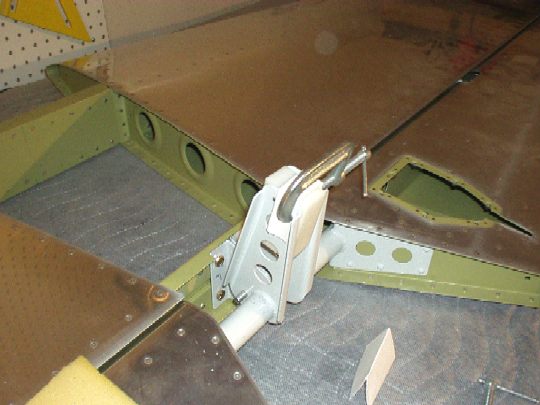
Installed the elevators with all five bearings, and clamped the
elevator counterbalance arms to the HS for "in trail"
alignment. (Note: used 1/2" thick balsa wood under the
clams, which provided enough rigidity so there's no slop, but enough
give to not damage the elevators or HS.) Found that the right
elevator horn was angled slightly aft of the left elevator horn, by
about 1/8" at the tips. This is normal (per builder's
manual) for the elevator weldments to not be perfectly matched.
The right elevator horn was also slightly shorter at the tip. So
the right elevator horn will be used to position the hole for the
pushrod bearing bolt, which will thereby ensure sufficient edge margin
on both left and right horns. Drilled a #30 pilot hole in the
right horn. Found that the distance between the horns is
approximately 1-1/32", and amazingly enough I had a block of
scrap delrin of that exact thickness. Drilled a #30 hole through
it, using a drill press / drill vise to ensure it is perfectly
perpendicular. Clamped it between the horns, using a the #30
drill bit to align the holes, and then used it as a drill guide to
drill the left elevator horn. Removed the elevators and enlarged
the holes to final size with a unibit.
 |
| 2006.12.30:
(12.0) [This log
entry is for the past week] Made spacers for the bolt that attaches
the push rod bearing to the elevator horns. The total span was
approx 1.0385", and the bearing is 0.5", so I made two
identical spacers of length approx 0.269". I first
rough-cut them from some aluminum tube stock, then spun them in the
drill press while pressing them down into sand paper to get them to
final size. This works pretty well, but that is about as short
as it will work because of how the drill press chuck is
designed. I then attempted to make spacers for the the bolt that
attaches the horns to the center hinge bearing, but these are too
short to make using the drill press. Hopefully Vay's lathe can
handle the job. These spacers need to be 0.226" long.
(Pretty amazing that the distance came out identical to within
0.001" between the center bearing and the left and right horns!)
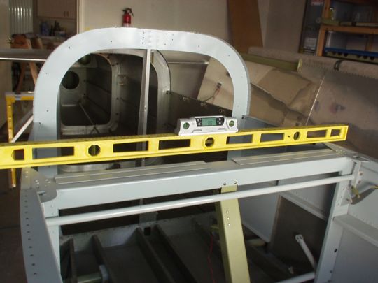
Now the really fun stuff -- fitting the HS to the fuselage. I
started by measuring and marking important reference lines on the aft
deck. I found that there is some amount of slop in how this area
was constructed (QB of course!) in that the aft deck is not quite
centered with respect to the longerons, the bulkheads are not exactly
perpendicular to the centerline of the airplane, etc. Real
close, but different enough that for this purpose I wanted to make
sure I used the most appropriate structures for reference.
Anyway, I measured, measured, and measured some more until I had
everything sorted out. I measured and verified the corresponding
bolt locations on the front spar of the HS and the mating structures
on the fuselage (longerons and bulkhead reinforcements). After
literally hours of this tedious measuring and drafting, I, with
Stacey's help, finally placed the HS on the fuselage for a real live
fit check. [Note that despite what the manual says, you really
need to have the shims to do all the fit checks and drilling.
Otherwise, the HS fwd spar will be resting on top of dome rivet
heads.] Got everything centered up, and verified symmetry by
measuring from identical locations on the tips to identical locations
in the fwd fuselage. I also leveled the fuselage laterally, and
then verified that the HS is level. With good fit verified, I
removed the HS and on the bench drilled pilot holes for the bolts in
the fwd spar. Clamped the HS to the fuselage again, did another
symmetry check, and started drilling. Did the outboard
holes using long drill bits, then the inboard holes using an angle
drill. Finally, I located the holes on the F-711C bars and
drilled them through the bars and aft spar. With everything now
bolted down, I did one more symmetry check, which matched within about
1mm, or about 0.25º of sweep. I also checked again for level,
which was perfect as best as I could tell with my 4' bubble level.
With the HS still on the fuselage, I installed the elevators with
Stacey's help. Initial fit is pretty good, but I'll want to make
a couple of minor adjustments. The cutout in the aft deck for
the elevator horns was cut 2" wide (QB). This is marginally
sufficient, providing about 1/32" clearance to the left horn and
just slightly more to the right horn. Problem is that the
elevator down deflection limits out with the horns hitting the
radiused corner of the cutout instead of the straight bar of the
stop. As is, they limit out at about 21º, which is within spec
(20º to 25º), but I want them to limit out properly against the
bar. Will widen the cutout to fix this problem next time I
remove the HS from the fuselage. The up deflection limit is
currently about 30º, with the horns hitting the aft bulkhead.
This will allow me to set the stop within spec (25º to 30º). |
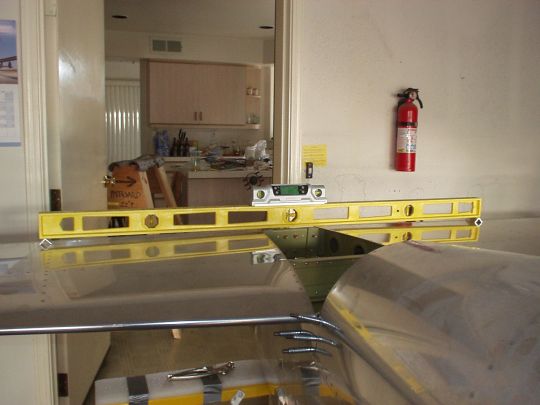
| 2007.01.07:
(16.0) [This log
entry is for the past week] Fitting the vertical stabilizer to the
fuselage. Firstly, I removed the HS from the fuse and fitted the
F-781 VS attach plate to the front spar of the HS (much easier done on
the bench than in assembly). While I had the HS on the bench I
took care of other loose ends from the HS that were more easily done
disassembled (see previous entry). Re-installed the HS on the
fuse and continued with the VS. In fitting the VS rear spar to
the fuse, I deviated somewhat from the sequence described in the
builder's manual. I made the F-712D angle (VS mount and
up-elevator stop), but only drilled the holes, did not trim the legs
yet (this will turn out to have been good foresight). Bolted it
to the fuse. I carefully measured and marked references on the
VS rear spar, and clamped it to the F-712D. Got it perfectly
vertical by measuring from the VS tip to the HS tips, and
match-drilled the upper two mounting holes using F-712D as the drill
guide. I then drilled the lower four mounting holes using the VS
rear spar as the drill guide, since I've already installed the tie
down block. This is the deviation from the manual, which worked
out really well. The key to it though was very careful measuring
to ensure that the mounting holes ended up in the right spot on the
tie down block. Not much room for error.
I proceeded to the VS fwd spar, which turned out to be a little more
tricky than I thought. Firstly, I found that I had to make an
0.040" spacer between the spar and the F-781 (this possibility is
noted in DWG 27A). I then very carefully found the centerline on
the VS leading edge, and likewise on the top of the fuse. I then
marked another longitudinal line on the fuse, 1/4" left of
center. The leading edge of the VS should be offset by that much
to counteract the plane's left turning tendencies. Got
everything clamped down and rechecked all the measurements. Then
checked the the hinge line in the back, because the VS rear spar is
actually quite flexible and can easily be made non-straight by
mounting the front spar higher or lower. I checked the hinge
line first by holding a taught string through the centers of all three
hinge brackets. Then checked with the real thing by mounting the
rudder. The rudder fit perfectly and swung freely with now
discernable resistance. I started drilling the holes through the
front spar using the pre-punched holes in F-781 as a drill
guide. This area is cramped and requires use of an angle drill,
which was very awkward. Unfortunately, 3 of the 11 holes turned
out quite elongated. This is a structurally important area, so
I'll really want to fix it right. |
| 2007.01.13:
(4.0) [This log
entry is for the past week] The three holes in the F-781 were pretty
bad, but the holes in the thinner VS spar and spacer looked ok.
I though of a few ways to fix it:
1. Drill out the holes for AN470AD5 (5/32") rivets. That
should be big enough to get back to nice round holes. But I
don't have any 5/32" rivets or squeezer sets, and they might take
a lot of force to squeeze.
2. Drill out the holes for AN3 (3/16") bolts. That should
work, but adds weight. Last resort.
3. Get a new F-781 and see how closely the pre-punched holes fit the
holes already drilled in the VS spar. If they're not close
enough, then
4. Get or make a new F-781 without pre-punched holes. Use the VS
as a drill guide.
I shot an email to Van's describing all this to get their
recommendation. Their answer was to the effect that 3 messed up
holes out of 8 is ok. Rivet them and don't worry about it.
I wasn't satisfied with that. I went for a multi-pronged
approach to see which of my ideas would work best. I got some
5/32" rivets and a squeezer set. I was able to squeeze down
a rivet almost to spec, but not quite. The squeezer yokes aren't
stiff enough, so they just flex out. Still, I got the shop head
almost to spec, probably good enough. I also bought a new F-781
from Van's, and found that the holes lined up pretty well. I
used the original F-781 to located the four HS attach bolt holes in
the new F-781, and moved on.
Lessons learned:
1. Be even more careful with the angle drill. Enlist a helper as
another pair of eyes to make sure it's straight.
2. Clamp the VS to the F-781 and remove together from the
fuselage. On the bench I still would have had to use the angle
drill, but perhaps it would have been less awkward.
3. Van's should not have made the holes in F-781 pre-punched.
Had they not been pre-punched, they could have been drilled in
assembly from the other side. I.e. from aft to front, from the
VS spar, through the spacer, through the F-781. This is much
more accessible and would not require an angle drill even in
assembly. And better yet, on the bench it would be a piece of
cake. |
| 2007.01.14:
(4.0) Removed the
VS and reinstalled the elevators for another fit check after
increasing horn clearance through the aft deck. Looking
good. Removed the F-712D elevator stop for trimming. In
studying the plans (DWG 27A) I found that the dimension callouts would
violate edge distance on the bolt holes. Doesn't look like added
length would interfere with anything, so I decided to adjust the
dimensions for good edge clearance. Also before trimming I did a
fit check of the elevator up deflection, and found that as is (F-712D
un-trimmed) it was spot on at about 27.5º (specified range 25º to
30º). Had I trimmed it per DWG27A, the elevator horns wouldn't
even hit the stop. They would bottom out on the aft bulkhead
first. Score another one for "measure twice, cut
once".
Did a first fit check of the elevator pushrod. Attached it to
the elevator horns, so far so good. Attempting to attach the fwd
end to the bellcrank, I found that the "fork" of the
bellcrank was way too narrow (required: 0.500", actual:
0.395"). The width of the fork is set by bends that were
done at the factory, and can't easily be adjusted in assembly.
When I make a new bellcrank, I'll check and adjust them before
riveting. (I planned on making a new bellcrank anyway for two
other reasons: 1. The flange bearing has side-to-side play.
Others have reported the same problem, hopefully I can get a new good
bearing from Van's. 2. I'll want to make provisions for a third
pushrod that will attach to an autopilot servo.) |
| 2007.01.21:
(8.0) [This log
entry is for the past week] Started making the rudder stops. On
my fuse, the lower forward rivet that attaches the rudder stop is
already installed, so I decided to extend the rudder stop forward and
add two more rivets (upper and lower). Otherwise, I made the
stops per-plans, although initially I didn't trim the part that'll
make contact with the rudder horn, so I can fine tune it to my
fuse. That turned out to be good foresight, but still not
enough. To achieve the correct travel limits (1.125" from
the aft inboard corners of the elevators) the contact point on the
stops would be about 1/4" further aft than shown on the
plans. Searching the web forums, I found that this is
common. The problem is that this leaves only a very small
contact area between the stop and edge of the rudder horn. That
would cause a high stress area on the rudder horn, and potentially the
rudder horn could even slip past the stop with enough flexing.
So I decided to throw away the stops and make new ones that also
extended further aft. This worked out nicely. Note also
that the fuselage is not flat where the stops attach, so that leg of
the angle has to be shaped to match the contour of the skin. Not
so easy on 1/8" thick aluminum angle. I did this by putting
the angle in a vice and beating on it with a mallet. That was
fun! Drilled the stops to the fuselage and
trimmed them for the correct rudder travel. More trimming and
finishing still needs to be done for smooth interfaces to the
fuselage. |
| 2007.04.17:
(40.0) [This log
entry is for the past several weeks. Time logged is a gross
estimate. I've been very busy at my day job, so work on the
plane has slowed down considerably, but I have been working on it
little by little. Just haven't kept up in logging every work
session.]
Adjusted the fit on the rudder. With the rod end bearings set to
the depth shown on the plans, there was a considerable gap between the
rudder and VS. I was able to bring it in closer by about two
half-turns on the rod end bearings for a closer fit, without creating
any interference. Note that at the extreme left deflection, the
rudder does contact the left aft VS skin slightly (both before and
after adjusting the fit, no difference) but with no potential for
binding so I won't worry about it. I also fitted the fiberglass
rudder bottom, just to make sure it doesn't create any
interference. See section on fiberglass fairings.
After several times of installing and removing empennage pieces from
the fuse, the aft deck had a few minor scuffs and scratches.
This was a good excuse for me to strip off Van's "wash
primer" and give it a coat of AKZO. Also sprayed the inside
skin aft of the aft bulkhead, and the outside skin where the rudder
stops will mate. Sprayed the stops themselves and the other
miscellaneous brackets, shims, and spacers used in the empennage
attach.
Before riveting the rudder stops to the fuse, I decided to make and
fit a rudder gust lock. My design is simple and compact: a piece
of 5/32" music wire (a high-carbon steel alloy) bent to a square
U shape, that gets inserted one end into a hole in the left rudder
stop and the other end into a hole in the left rudder control
horn. The span of the lock is 3", and the "pins"
are 2.25" long (somewhat arbitrary). It inserted from the
top, and held in by gravity. Before making the final bend, I
slipped a piece of aluminum tubing (OD: 3/8", ID: 1/4", L:
0.400" ) around the rod that will be held captive when the bends
are done. A key chain ring can then be put through that ring to
attach a "REMOVE BEFORE FLIGHT" flag.
Finished the rudder stops and riveted them to the fuselage. Note
a few deviations from Van's plans: Extended the stops aft of the edge
of the skin, so that they actually make solid contact with enough
material on the rudder horn (many builders have found this
necessary). Extended the material forward to add another pair of
forward rivets, because one of the forward rivets called out has
already been installed. Added another pair of rivets at the very
aft end of the skin (past the bulkhead) to hold everything together
nice and tight (the fit in this area is otherwise loose and sloppy on
many RV's). Beveled the the stop to create a smoother interface
with the skin on the forward, aft, and bottom sides (maybe that's
worth another 0.1 knot, and it also looks better). Anyhow, I've
spent a surprising number of hours on this little part, but I'm very
pleased with the results. |
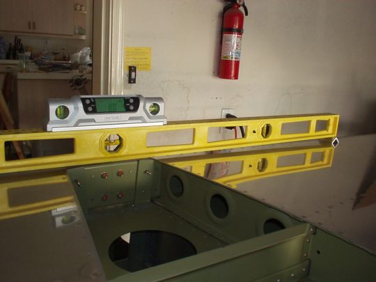
| 2010.11.10:
(0.0) Although
I've checked this while I first fit the empennage, I thought I'd take
the opportunity again, while I've got the fuselage leveled and the HS
installed, to check that the HS is laterally level. It is.
 |
|
|