|
  

Stick Grips
Running Total Hours:
0.0
 | 2008.03.15:
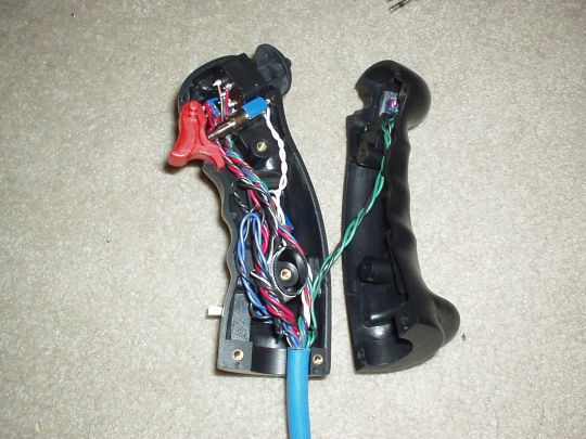
(0.0) I selected the
military-style stick grips made by Infinity Aerospace. The
design of these grips is closely modeled after those found in many 3rd
generation American jet fighters, such as the F-4 Phantom II.
They are contoured to fit the shape of the hand, and have a number of
switches strategically mounted for easy access right on the
grip. The idea is that the pilot can access various functions
without having to look down into the cockpit or fumble to reach for
switches on the instrument panel. The military term for this
concept is HOTAS: Hands On Throttle And Stick. Makes good
sense. The main differences between the Infinity grips and their
military cousins are:
1. The Infinity grips are scaled down slightly compared to the
military grips, to be more comfortable for an average human's hand,
and not wearing gloves.
2. The Infinity grips are available in a right-handed version (like
the military grips) and also a left-handed version that's a mirror
image. The left-handed grip is better suited for the left seat
of a side-by-side airplane with a center throttle, like the
RV-7A. Mine will have a lefty on the left and a righty on the
right.
3. The Infinity grips, while certainly not cheap (about $175 each),
are a lot cheaper than the genuine military grips. They also use
standard switches in commonly available form factors instead of exotic
and expensive mil-spec varieties.
Infinity Aerospace, incidentally, is a local company based at
Gillespie Field. And the man behind the company is J.D. Newman,
a retired U.S. Navy F-14 pilot. When I came by his hangar to
pick up my grips, he showed me his own airplane project, retractable
landing gear hardware that he designs and sells, and other projects he
has in the works. Cool stuff!
 |
| 2008.04.10:
(0.0) Started fitting
the grips to my stick tubes.
First it should be noted that the left and right sticks on the RV-7A
are not the same. The left hand stick is a single welded
assembly that is non-removable, with a stick tube that is 1"
outer diameter, and approx 0.035" wall thickness
(measured). The right hand stick is in two pieces: a base and a
removable stick tube. The stick tube itself is 7/8" outer diameter,
and apporx 0.050" wall thickness (measured). The Infinity
grips are designed to fit over a 1" diameter tube, so the left
stick is good as is. For the right stick, I bought a spacer that
Infinity sells for exactly this purpose.
Stick length in the RV's is a contentious issue. In RV-6 and -8
series aircraft, there are interference issues between the sticks and
the panel and/or other structures in the cockpit, and therefore
builders are often forced to shorten the sticks to remove the
interference. In the RV-7 series there is no interference
issue. Still, many -7 pilots report that they prefer the control
feel and ergonomics of a shorter stick to the stock length.
Van's strongly discourages this practice (see articles in the
RV'ator), noting the effects on control sensitivity and stick
forces. I decided to act conservatively and keep essentially the stock
length. I can always slide my hand down the stick below the grip,
as some do, at appropriate phases of flight. And if at a later date I do
decide to shorten the sticks, that's always an option.
Having said all that, I did have to shorten the stick tubes in order
to keep the same effective stick length once the grips are
mounted. The Infinity grips are designed to slip over only
2.125" of the tube, and there is another approximately
2.875" from there to the top of the hand in its natural
position. I decided somewhat arbitrarily that the natural hand
position on the bare stick tube would be with the top of the hand at
0.5" below the top of the tube. So to maintain the
equivalent hand position with the grips, I had to shorten the tubes by
3.375". Note also that the left and right stick tubes
weren't exactly the same length to begin with (other builders have
reported the same). The left stick was about 0.5" longer
than the right stick. This difference isn't meaningful, but
rather just falls within Van's generally loose design and
manufacturing tolerances. Anyway, I took the average of the two
as the nominal length, and so I trimmed the left stick tube by 3.625"
and the right stick tube by 3.125" to achieve approximately the same
nominal stick length on both sides.
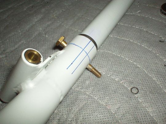
The top of the stick tube then needs to have two 29/64" holes on
the left and right sides, 0.5" from the top, to receive a lug on
the inside of the grip that keeps it from rotating or sliding up the
tube. And a 0.5" wide notch on the aft side, from the top
down 1.25", to provide a channel for the 17-conductor
cable. But per J.D.'s advice, and that of other builders, the
ideal orientation of the grip is not at right angles, but rather rotated somewhat so that it is more in line with the forearm.
This way, there is less or no bending in the wrist (at least in the
neutral position), making it more comfortable. I'll want to just
sit in the airplane and play with it to find the most comfortable
angle for me. So for now I've only cut the holes and notch
in the right side stick tube, which is free to rotate until I drill
the hole for the bolt that secures it to the bottom piece. I'll
use the right side stick to do this because with
the left hand stick, being non-removable, there is no such
freedom.
 |
| 2008.04.14:
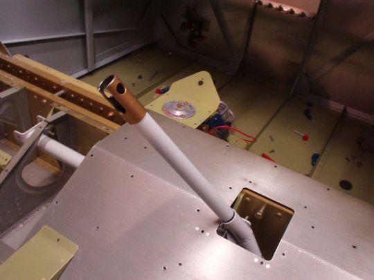
(0.0) Stick grip
orientation.
I installed the right side stick in the airplane, installed the seat
floors, and dropped in a makeshift seat cushion (a folded up furniture
blanket). I set a ladder next to the airplane and -- for the
first time ever -- climbed into the cockpit. Playing with the
stick a little bit (and really enjoying it!) I found that 1) indeed it
is uncomfotable with the grip oriented straight ahead, and 2) the most
comfortable orientation for me was with the grip rotated about 22.5°
counter-clock-wise, putting it more-or-less inline with my forearm.
Armed with this information I went ahead and cut the notch and
mounting holes in the left hand stick, orienting the grip at 22.5°
clock-wise. I also then drilled the bolt hole that secures the
right side stick tube (F-669) to the base (WD-611), orienting the
right side stick at 22.5° counter-clock-wise.
Note that the bolt securing the right side stick tube to the base is
not in the original plans. It is specified in Van's service
bulletin SB 07-2-6, which was issued as a result of -- you guessed it
-- an accident caused by the stick tube popping out of its base during
a landing. Now, one might say having some means of securing the
stick to its base would seem like common sense. I for one would
agree. But apparently it didn't occur to Van's, and to at least
one builder [and probably many more], until the inevitable actually
occurred. This example illustrates why I will continue to fix
potential problems as I find them, despite Van's and many in the
builders' community insisting that "it's never been a problem for
me, so
don't worry about it."
 |
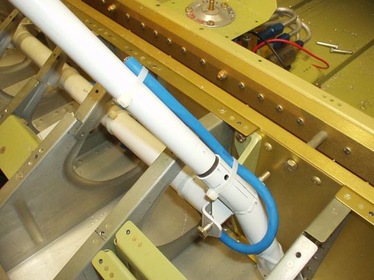
| 2008.09.01:
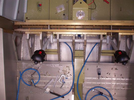
(0.0) I started
examining my options for routing the cables from the sticks toward the
panel, and quickly realized that this will not be a trivial
task. The problem is that the cable is so thick and inflexible
that it is almost impossible to have it transition from the stick to
an unmoving part of the airframe without it either putting noticeable
forces on the stick, or having excessive free-floating cable that
would chafe or potentially interfere with other moving parts
associated with the flight controls.
I experimented with various ideas by zip-tying a length of cable to
the stick and playing with the cable routing. The most promising
approach was actually to have the cable exit the stick on the forward
side, part way up, and be secured with zip ties down the stick until
it becomes free near the axis of rotation, but oriented straight
down. From there it loops around and is then secured to the
torque tube, following it inboard. Then, it makes another
transition from the torque tube to an unmoving part of the
airframe. The advantage of this approach is that instead of
making one transition with two axes of freedom, it makes two separate
transitions each with only one axis of freedom. Each is
therefore geometrically simpler, can be accomplished in smaller space,
and can more easily be accomplished without imposing noticeable forces
on the stick. The disadvanted however is that this routes the
cables right through the heart of the flight controls area, and if the
cable came loose somehow (zip ties break, etc.) it could potentially
jam up the controls.
As an alternative, I am now considering puting active electronics in
the stick tube itself to scan the switches and transmit serial data
back to the panel. That would relieve me from having to route
that humangous cable around the cockpit, and instead I'll only have to
deal with a much smaller and more flexible 3-conductor cable (power,
ground, serial data) instead. It also relieves me from having to
drill a very big exit hole for the cable in the wall of the tube,
which makes me somewhat uneasy, structurally speaking. We'll see, I'll put this aside for
now. |
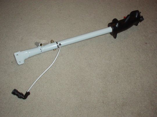
| 2009.03.03:
(0.0) Lots of
activity over the last few weeks, but I'll just summarize. I
decided to go with the serializer idea, and I've got it built. I
won't go into too much technical detail here, but basically I designed
and built a serializer board as I described previously. It scans
the switches and transmits their state over RS-232 at a rate of appox
300 samples/s. The physical dimensions of the board are approx
4" L × 0.75" W, and I enclosed the whole thing in
heat-shrink tubing for added protection. It nestles nicely
inside the stick tubes.
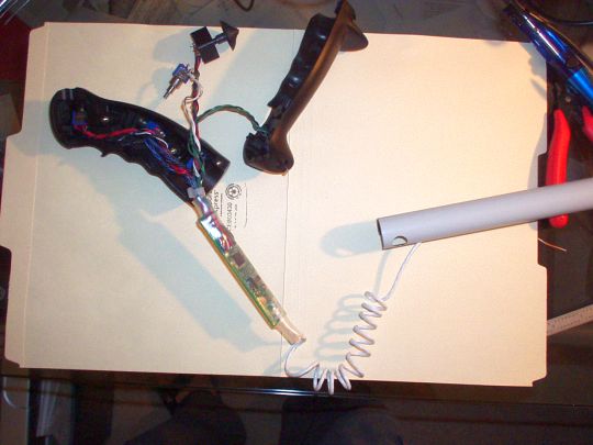
Out the bottom comes a 3-conductor 24
AWG shielded cable to a 4-pin M8-size AMP/Tyco Miniature Circular
Plastic Connector ("Miniature CPC"), making the stick easily
removable from the fuselage. The pinout of the connector is as
follows:
| Connector pin |
Cable conductor |
Board J2 pin |
Description |
| 1 |
1 (white) |
1 |
Power (operating voltage +4V to
+60V) |
| 2 |
2 (white/blue) |
2 |
Serial data (RS-232) |
| 3 |
3 (white/orange) |
3 |
Ground |
| 4 |
shield |
n/a |
Shield (should be grounded at main
board) |
Ultimately the stickgrip
serializer cables will connect to a main board in the forward cockpit
that will receive the switch states as well as other airframe sensor
inputs, and will control the various airframe actuators: flaps, trim,
fuel pump, lighting, and interface to avionics. For now, I just
made a little adapter cable and test program so I can plug the
stick grips into a PC to test them. All looks good.
Just a few details about the board design process:
CAD Tools: I used the open source gEDA tool suite on Linux to create
the schematics and board layout. This is the first time I've
used the gEDA package, and I found it to be a mixed bag.
Compared to the commercially available tools I've used before (OrCAD,
Pads, etc.), the gEDA tools are definitely less user-friendly and more
rough around the edges. But after a bit of a steep learning
curve, I actually found them quite useable, at least for a simple
design like this. One big upside to the gEDA tools is that their
design files are all just formatted ASCII. This facilitates
creation of my own helper scripts, which I did, and also makes it
possible to diff two versions of a design file. I'm a big
proponent of that!
Board FAB: I used www.4pcb.com to
fab the boards. Good prices at prototype quantities, good
manufacturing quality, automated DFM checker for gerbers uploaded to
their website, and a quick turnaround, delivered as promised.
This was my first time using them, and I would use them again.
Board assembly: Did this myself. I currently don't have easy
access to professional assembly/rework lab, so I set up a basic lab at
home. No microscope... but thankfully I have good eye sight and
was able to solder the fine-pitched parts without too much difficulty.
|
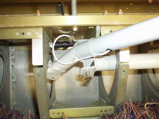
| 2008.04.16:
(0.0) Fitted the
stick grips into the fuselage, which meant mounting a mating connector
into the seat ribs and then adjusting the stick grip's cable to
provide the desireable routing and freedom of motion. I then
zip-tied the cable to holes I had drilled in the stick to provide
strain relief and hold the cable at the correct position.
|
|
|