|
  

Rudder / Brake Pedals
Start:
2005.08.05, Completion:
in progress, Hours:
19.5
 | 2005.08.04:
(1.0) Prepared and fitted the F-xxxx
bracket that holds the brake lines on the firewall. |
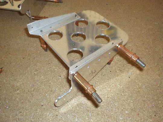
| 2005.08.16:
(1.0) Started working on the
brake pedals, deburring the F-6117BPP brake plates... |
| 2005.08.17:
(1.0) More deburring on the
brake plates and F-6117A side plates... |
| 2005.08.18:
(2.0) Done deburring the brake
plates and side plates. |
| 2005.08.20:
(1.5) Cut the F-6117C angle
angles from stock and match-drilled to the brake plates and side
plates. |
| 2005.08.21:
(1.0) Trimming and deburring
the F-6177C angles... |
| 2005.08.22:
(1.0) Trimming and deburring
the F-6177C angles... |
| 2005.08.23:
(1.0) Done trimming and deburring
the F-6177C angles.
 |
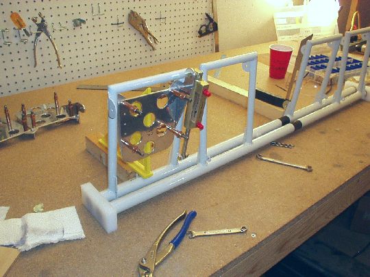
| 2005.08.28:
(1.5) Enlarged the holes for
the brake pedal hinge bolts to final size. Note that the two
holes in each pedal need to be co-linear so that they can rotate
smoothly about the hinge axis. Since the side plates and
reinforcing angles are not quite perpendicular to the hinge axis, I
drilled/reamed the holes with the pedal assembled, jigging it so that
the drill is perpendicular to the vertical centerline of the
pedal. Did a fit check to the rudder pedal weldments -- all
good. |
| 2005.08.29:
(1.5) Started fitting the
master cylinders in assembly with the rudder pedal weldments and the
brake pedals. Setting the geometry such that in the neutral
position, the left and right rudder pedals are angled equally to
center up, i.e. forming an isosceles triangle with the plastic
bushings. In this position, the brake pedals are set along the
centerline axis of this triangle, i.e. perpendicular to the plastic
bushings. Note that in the airplane the plastic bushings (and
the stringer they're mounted to) are not quite parallel to the
longitudinal axis of the airplane, so all the geometry described above
is relative to that plane and will be tilted by a few degrees when
mounted in the airplane. One pedal done, three to go.
 |
| 2005.08.30:
(3.0) Fitted the master
cylinders for the remaining three pedals. Match-reamed all rivet
holes to final size. |
| 2005.09.06:
(2.0) Alodined all the
pieces of the brake pedals. |
|
2005.09.07: (1.0)
Sprayed AKZO on all the pieces of the brake pedals. [also parts
for primary flight controls, but here I'll log 1.0 h attributed to the
brakes] |
|
2005.09.07: (1.0)
Riveted the brake pedals. |
| 2006.02.07: (0.5)
Drilled the bolt holes through one of the plastic bushing
blocks. Unfortunately I used a newly acquired drill press vise
from Harbor Freight. At $7 you don't expect high quality tools,
but what could be so bad about a drill press vise? As it turns
out, the jaws aren't quite perpendicular to the base. So I ended
up with bolt holes that weren't quire straight through the bushing
block. So this $7 tool has now cost me $14 dollars, the other $7
being a replacement part from Van's. |
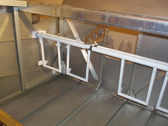
| 2006.02.08: (1.0)
Armed with a new drill press vise from Sears ($40), I drilled the
other bushing block which came out perfectly straight. I then
used the bushing block as a drill guide for drilling the left side
longeron. I drilled a total of 6 holes for 4 possible fore-aft
positions, starting at the most forward location shown on the plans,
and back in 1-5/8" increments (half the center to center distance
between the holes in the bushing block).
Note: I used a 12" long 3/16" drill bit, squeezed in between
the skin and the longeron which are not yet riveted together.
 |
| 2006.03.31: (1.0)
Drilled a new bushing block for the right side. The dimensions
of the new bushing block are measurably bigger than nominal, as was
the case with the replacement bushing block I bought for the flaps
actuator. The edges are also not as clean as the original.
What's going on? Anyway, I made sure the hole spacing is still
nominal so it would be interchangeable. Drilled the longeron
(same technique as the left side). |
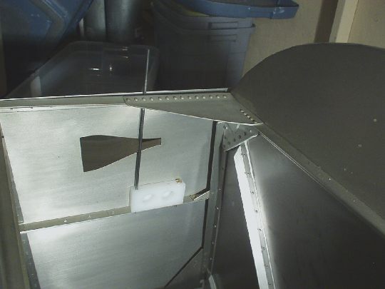
| 2006.04.02: (1.0)
Drilled the center support bracket to the firewall upright. I
carefully clamped it in position, sliding the pedal tubes back and
fourth in the bushings along the longerons to ensure that the bottom
of the bracket is positioned in the right plane.
There is a comment in the builder's manual about locating the rivet
holes so that they don't interfere with the rivets for the firewall
recess along the other leg of the upright angle. It's not clear
to me how they would interfere, even if they're right abeam each
other. But nevertheless I offset the holes a little to separate
the rivets from each other. Probably unnecessary. |
| 2006.04.03: (1.5)
Drilled the bolt holes in the center support bracket for the plastic
bushing block. I could only do this for the three forward
positions that I drilled on the longerons. The center support
bracket wasn't long enough for the fourth (aft) position. Oh
well.
The method I used was this: Mark the centerline on the bushing
block and the corresponding line on the the center support
bracket. For each of the three forward positions: 1) install the
pedals in position on the longerons, 2) place the upper half of the
center bushing block on the tubes, 3) cleco the center bracket to the
firewall, 4) adjust the bushing block and center bracket so they line
up properly and clamp them to each other, 5) remove the bracket from
the fuselage with the bushing block clamped to it, and finally 6)
match-drill using the bushing block as a drill guide. A lot of
steps, but results in a perfect fit in all three positions.
I did run into one snag... The bolt holes in the center bushing
block are 1/4" closer together than the bolt holes in the
outboard bushing blocks, resulting in a hole pattern in the center
bracket that is different from the longerons. In the longerons,
the aft bolt hole of the first (forward) position doubles as the
forward hole of the third position. But in the center bracket,
these are different holes, 1/4" apart center to center.
Being 3/16" holes, this obviously violates normal hole
spacing. But I concluded that in this application there should
not be significant stresses that would cause a problem. |
| 2006.04.04: (2.0)
Trimmed, cut the lightening holes, and edge-finished the center
support bracket.
 |
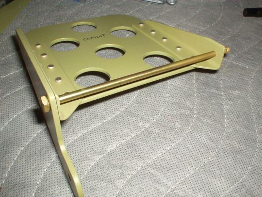
| 2007.04.17: (0.0)
I've had some reservations about the design of the rudder pedals, and
potential for binding. The problem is that the hinge points for
the pedals (as well as the master cylinders) are just two adjacent
pieces of metal with a bolt through them. For the pedals this is
potentially problematic because force applied to the pedal will tend
to twist the left and right bolts so that they're not co-axial.
Also, just the idea of rotating around a steel bolt as a
"bushing" is far from ideal. Now recently I've read
some threads on the VAF forums discussing people actually having
problems with the brakes dragging because the pedals don't always
return all the way to neutral. Some people have remedied the
problem by adding beefier return springs to the master cylinders, but
to me that seems like a band aid and not a cure. I decided a
design change is definitely called for.
First of all, the short bolts on the left and right hinge points will
be replaced by a single long bolt (AN3-56). These are available
from Spruce at almost $10 each (ouch!), but so be it. Then, I
want to add a better busing surface between the bolt and the
pedal. I found some plastic flange bushings on McMaster-Carr and
at Marshall's Industrial Hardware that might do the job nicely.
Problem is I need to make room for the bushings' flanges by either
spreading the mounting flanges on the rudder pedal weldments or by
machining down some clearance in the brake pedal flanges. TBD. |
| 2007.06.01: (0.0)
After some experimentation, the best solution seems to be just the
long bolts with no plastic bushings. I still like the idea of
the plastic bushings in principle, but none of the bushings I was able
to find or make worked very well. So with metal to metal contact
around the bolts, I'll just have to make sure the holes are slightly
oversized so they rotate freely, and keep them lubricated to minimize
wear.
 |
|
|