|
  

Primary flight controls
Start:
2005.07.10, Completion:
in progress, Hours:
18.0
 | 2005.07.10:
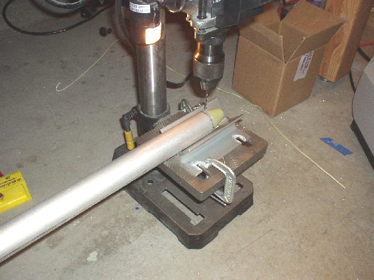
(2.0) Cut the aluminum and steel
tubes for the aileron and elevator pushrods. |
| 2005.07.14:
(3.0) Primed the insides of the
pushrod tubes by sloshing with AKZO. Also alodined and primed
the machined aluminum end caps of the pushrods. Later in the
day, started installing the end caps. Fit on most was tight, so
I chilled the end caps in the freezer and heated the ends of the tubes
to make the best of expansion and contraction. This, along with
some gentle taps with a mallet did the trick. Started riveting
some of the end caps using a tube drilling jig I got from Spruce. |
| 2005.07.15:
(2.0) Installed a few more of the
end caps. Two to go. |
| 2005.07.16:
(1.0) Finished installing the
control tube end caps.
 |
| 2005.08.04:
(1.0) Bored out the inner diameter
of the brass bushings for the control sticks and aileron bell
cranks. Used Vay's lathe and a 1/4" reamer bit from
Cleveland Tools. |
| 2005.08.05:
(2.0) Fitting the bushings:
Shortened the length of the bushings to slightly longer (less than
0.0015") than the sleeves of the sticks and aileron bell
cranks. I'm not thrilled with this design, as there will always
be a little slop in the sticks because the bushings must be slightly
longer than the sleeves. Also, there's some difference between
the outer diameters of the bushings and the inner diameter of the
sleeves, both of which were cut to final size by Van's. Will try
using grease to fill the void.
My technique for squaring and shortening these bushings (and other
tubes, spacers, etc.) is to chuck the tube in the drill press and put
some 100 grit garnet sand paper over particle board on the drill
press's work surface. This lathe-like setup guarantees a square
edge and allows me to remove material in very small increments. |
| 2005.08.09:
(0.5) Made the W-929 aileron bell
crank spacers. Fitted them precisely using the technique
described above. |
| 2005.08.15:
(0.5) Purchased some Dow Corning
Molykote G-4700 "Extreme Pressure Synthetic Grease" from
McMaster-Carr. Used it to lubricate the brass bushings with good
results. The sticks have smooth action, and any slop has become
almost imperceptible. |
| 2005.08.15:
(1.0) Fitted the F-665 control
column push rod to the control column assy. DWG 38 top left
corner shows a dimension callout of 18 7/8" center-to-center of
the rod end bearings. But using this dimension causes the sticks
to be tilted inward, i.e. toward each other at the top, in the neutral
position. I think they should be parallel as shown on DWG 38
view A-A, which requires the dimension callout be shortened to approx
18 5/8". Will run this by Van's tech support. |
| 2005.08.16:
(1.0) Fitting the WD-610 control
column to the fuselage. First test fit showed that a total of
just under four (4) AN960-10 washers are needed on the outside of the
bearings. However, three (3) AN960-10 washers and one (1)
AN960-10L washer is still shy. I'll need to either grind down a
washer of fabricate a shim to get this just right. |
| 2005.09.04:
(1.0) With Stacey's help,
alodined the elevator bell crank pieces and spacers. |
| 2005.09.07:
(1.0) Sprayed AKZO on the elevator bell
crank pieces and spacers. [also brake pedals, but here I'll log
1.0 h attributed to primary flight control parts] |
| 2005.09.07:
(1.0) Riveted the elevator bell crank
and test-fit in the airplane. |
| 2006.01.03:
(1.0) Cleaned, abraded, and sprayed
AKZO on the outside of the push rod tubes. |
| 2007.04.17:
(1.5) Removed the F-633 control
column mounts from the fuselage so that I can cut out material called
out in the plans for "optional weight savings". I
suppose that for the QB factory, "optional" means "skip
it". For me, it's worth the effort. Every ounce
counts. Now to be clear, I fully expect that my airplane will
come in on the average to slightly heavy side because of the
powerplant and other equipment I plan to install. The tradeoff
of weight for functionality is pervasive throughout any aircraft
design. What I don't want to do though, is carry around dead
weight just because someone didn't want to spend a couple of extra
hours in the shop.
Cut the 1/2" holes (1/4" corner radius) using a unibit in
the drill press. Then spent some quality time with the band saw
(it doesn't cut through 1/4" aluminum very easily, and generates
a lot of heat, so I had to go little by little). Then some more
quality time with the files. One done, one to go. |
| 2007.04.21:
(3.0) Finished trimming and cleaning
up the control column mounts.
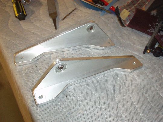
Sprayed AKZO on them, while the bearings are carefully masked
off. Installed them back in the fuselage. |
| 2007.07.01:
(2.0) I discovered several problems
with my elevator bell crank. 1) The "yoke" ends were
way too narrow. They were approx 0.4" wide (inner), and
they needed to accept 0.5" rod end bearings. I was unable
to adjust them sufficently and keep the yokes parallel. 2) The
flange bearing had a fair amount of slop. Other RV builders have
reported this, and according to Van's it's not a problem, but it just
doesn't seems like the amount of slop is excessive.
I decided to order parts and make a new bell crank. This time I
adjusted the bends before riveting so that the yokes came out exactly
0.5" wide (inner). I also extended the shim further down
toward the flange bearing, which will eventually allow me to attach
another control rod closer to the axis of rotation for the auto-pilot.
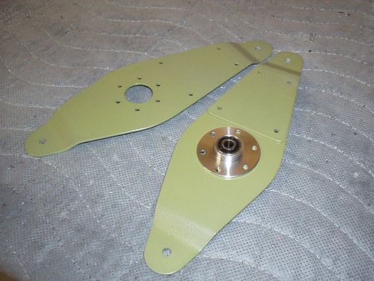
At the end of the day, it came out fine except that the new bearing
had just as much slop. I guess it's really just a shitty
bearing.
|
|
|