|
  

Cabin Frame Construction
Running Total Hours:
0.0
 | 2005.09.08:
(4.0) The F-721B aft canopy deck
and F-757 gusset have to be modified for the tip-up canopy.
Since they came already riveted on the QB fuse, they need to be
removed. Removed and started modifying them on the right side. |
| 2005.09.10:
(2.0) Removed and modified the left side
aft canopy deck and F-757 gusset. |
| 2005.11.04:
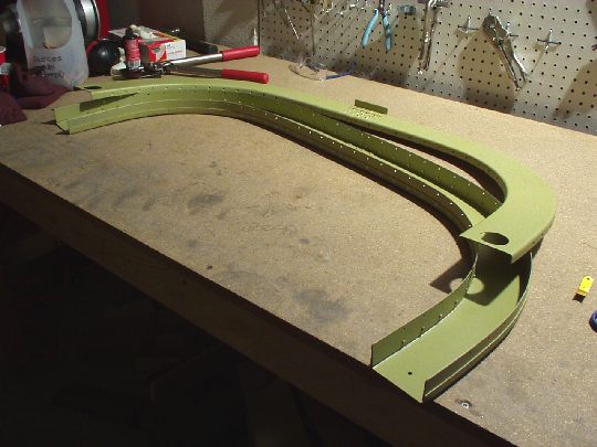
(1.5) Starting on the cabin
frame. Cut the F-631D from stock
and filed down to final dimensions. |
| 2005.11.05:
(1.0) Cut the F-631C from stock
and started filing down to final dimensions. |
| 2005.11.06:
(1.0) Filing... |
| 2005.11.07:
(1.0) Finished filing the
F-631C brackets to final dimensions. |
| 2005.11.08:
(1.5) Fabricated the F-632D and
E brackets. |
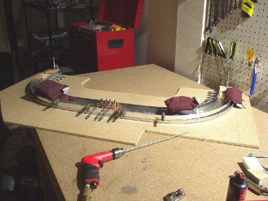
| 2005.11.09:
(1.5) Fitting the aft channels
to the specified dimensions. I created a simple fixture by
marking the dimensions on a piece of 3/8" particle board.
The channels can then be fitted and then clamped to the board, thereby
providing stability but allowing me to rotate the work on the bench
for easy access.
Note: the manual states that the channels can be separated slightly in
order to achieve the required width, 42 5/32" nominal. The width of my fuselage
was actually slightly wider than nominal (required 42 8/32"), but the channels were still
oversized and needed to be trimmed. |
| 2005.11.10:
(1.5) Made the F-631E
plates. Match drilled the aft plate to the aft channels. |
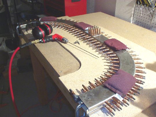
| 2005.11.11:
(1.5) Rounded the aft edge of
the top strap to nest in the curve of the aft channels. Started
match drilling them together. |
| 2005.11.13:
(1.0) Finished match drilling
the bottom strap to the aft channels. Rounded the aft edge of
the top strap to nest in the curve of the aft channels. |
| 2005.11.14:
(1.0) Started match drilling
the top strap to the aft channels.
 |
| 2005.11.15:
(1.0) Finished match drilling
the top strap to the aft channels. Removed the top strap and
filed down its forward edge around the curves where it lifted a
bit. This is so that the cabin frame will have a uniform
thickness (1.5" nominal) throughout. Rounded the forward
edge of the strap to nest in the curve of the forward channels. |
| 2005.11.19:
(1.0) Did the same to the
bottom strap. |
| 2005.11.21:
(2.0) Trimmed the fwd channels
where they mate at the center. Match-drilled the F-631E plate to
the fwd channels from the outside, all in assembly. Then started
drilling the fwd channels to the straps, maintaining the 1.5"
nominal thickness of the assembly to a tolerance of about -0",
+3/32". |
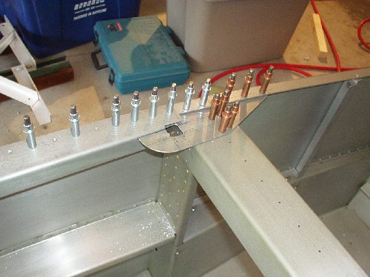
| 2005.11.22:
(4.0) Finished match-drilling
the fwd channels to the straps. Re-drilled all holes to final
size (#30).
Measured the width of the assembly again and it came up 42 4/32",
about 1/8" narrower than nominal for my fuselage. Looks
like the straps managed to pull the channels in just a bit, as can be
seen in the center joint between the L & R channels.
Hopefully this is within a workable tolerance for the final assembly
of the canopy. Note that I intend to put a thin elastic strip
(rubber?) between the cabin frame and the canopy anyway to allow the
canopy to "float" with uneven thermal expansion. So
maybe this amount of extra room will be just right.
Filed the bottom ends of the assembly square and to the called out
height. Disassembled and deburred the holes. |
| 2005.11.23:
(3.0) Countersunk the holes in
the fwd channels. I was worried this would be difficult because
of the curvature of the flanges, but it turned out to be no big deal
with the channel clamped to the workbench and the countersink cage in
the air drill. The countersinks came out nice and clean, no
chattering. I just had to check and adjust the depth on a hole
by hole basis to account for the variation in curvature.
As Murphy would have it, you always discover at the beginning of a
holiday weekend that you lack a necessary tool. The aft channels
need a 120° countersink rather than the standard 100° because they
take CS4-4 blind rivets. I thought I had this countersink bit,
but looks like I don't. So the aft channels will have to wait
while I order one from Cleveland Tools.
I proceeded to file down the flanges of the fwd channels to a uniform
width of 5/8" nominal. Note that toward the bottom of the
outboard flanges the flanges taper to a slightly narrower width.
This is how the parts came from Van's, an artifact of how the parts
were pressed. Shouldn't be a problem so long as I can maintain
edge distance when drilling the mounting brackets.
Also bent the F-732D angle to 88° as called out on DWG 39. |
| 2005.11.25:
(0.5) Drilled the F-732D
angle to the assembly. Now out of stuff to do on the cabin frame
until my 120° countersink bit shows up. |
| 2005.12.28:
(2.0) Countersunk the the
aft cabin frame channels with a 120° countersink for CS4-4 rivets. |
| 2005.12.29:
(2.0) Filed down the flanges
aft cabin frame channels to a 5/8" nominal width. |
| 2006.01.02:
(4.0) Surface prep / alodine
session: parts for cabin frame and for seat back brace on top of rear
spar bulkhead. |
| 2006.01.03:
(3.0) Priming session:
1. parts for cabin frame, 2. parts rat the top corners of the rear
spar bulkhead (removed and modified for tip up canopy), 3. parts for
seat back brace on top of rear spar bulkhead, 4. outside of flight
control push rod tubes. |
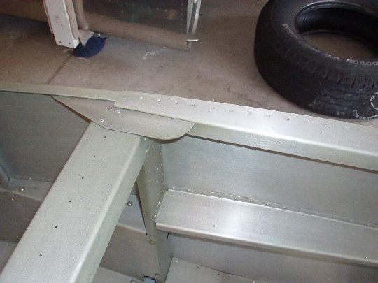
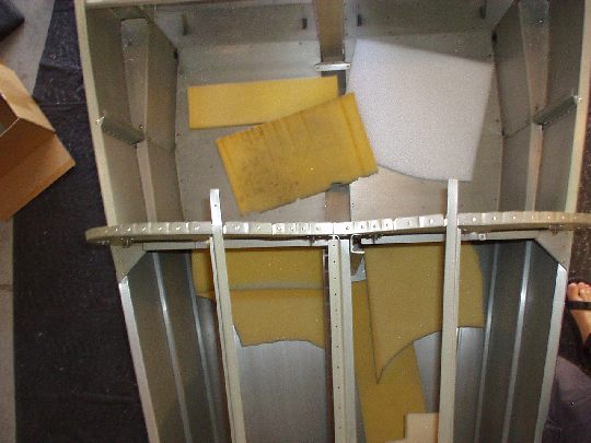
| 2006.01.04:
(4.5) Riveted the cabin
frame. Here's one last look inside before I closed it up.
 |
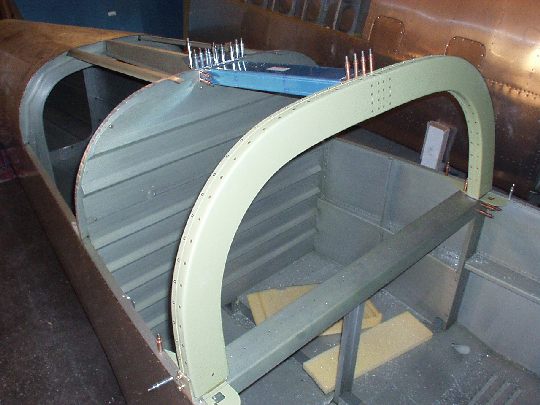
| 2006.01.05:
(4.0) Started fitting the
cabin frame to the fuselage. When I tried to cleco the aft top
skin to the fuselage, my suspicion was confirmed that the the F-786A
stringers ("J" stiffeners) protrude too far forward and push
the F-706 bulkhead out of position.
Looking at the aft end of
the stringers near the F-708 bulkhead I found that they weren't
necessarily cut long, but rather were positioned forward of where they
should be. I consulted with Van's tech support (Bruce) who
advised me that the slightly longer gap between the "J"
flange and the F-708 bulkhead is not structurally significant.
Judging the stiffness of the skin in that area purely due to its
curvature, I would agree. So, I proceeded to trim about
3/8" of the "J" flange at the forward end to provide
necessary clearance for the F-706 bulkhead in its correct
position. I used some scrap aluminum to protect bulkhead while
working on the stringer just millimeters away. I hate taking the
die grinder to a largely completed assembly (like the fuselage!!!),
but I was careful and this went without incident. |
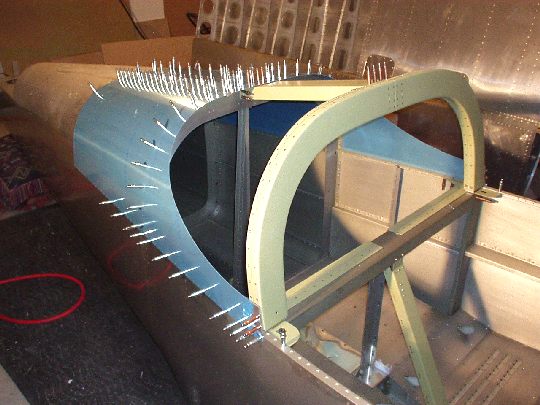
| 2006.01.07:
(1.0) Fitting the cabin
frame to the fuselage, I found that it is now too narrow span-wise by
about 3/32". It was dead on when it was clecoed and clamped
to the table, but apparently riveting snugged it up a little more and
pulled it in. A query to the Yahoo group revealed that this is a
very common problem. And a reasonable suggestion by some
builders that the cabin frame design could possibly be improved
instigated the usual holy war waged by the Van's worshipper camp
claiming that builder incompetence is the problem. Oh well.
One possible solution is to force the cabin frame into position by
tension from the mounting brackets/bolts. Some builders have
used this method and report success, but I don't like the idea of
building that much tension into my fuselage. Another possible
solutions is to use shims between the mounting brackets and cabin
frame. The issue here would be fit of the aft canopy between the
cabin frame and side skin. |
| 2006.01.10:
(3.0) While the debate
rages on the Yahoo group, I personally concluded that I could locate
the mounting brackets just a hair inboard without causing any problems
with fitting the side skin. And in doing so I got things close
enough that I could mount the cabin frame without shims and without
imposing any significant tension. |
| 2006.01.15:
(6.0) [This entry refers
to work done over a few days ... didn't keep up with the log]
Finished fitting the cabin frame and associated components to the
fuselage.
 |
| 2006.04.22: (2.0)
Benefiting from the experience of others, I received early warning
that the F-705G angle brackets will interfere with the shop heads of
the three most forward rivets of the top skin. So I marked the
locations on the brackets and relieved them using a Dremel tool.
Sprayed AKZO on the reworked areas. |
| 2006.05.07: (2.5)
Filed down the outboard faces of the F-631C brackets to be flush with
the contour of the fuselage. Countersunk the screw holes. |
| 2006.05.13: (4.5)
Test-fit the F-631C brackets with the cabin frame on the fuse, and
decided to take off just a little bit more material to get it just
right. Now it's perfect. Continued fitting the various
parts in the aft cabin... Put the F-774 skin on and used it to
match-drill the forward screw holes in the cabin frame mounts and also
the holes in the area where the F-732 assembly connects to the
bulkhead.
While I have the skin on, I'll also use it to
match-drill the top stringers. I had to trim the fwd ends of the
stringers some more to get them to fit right laterally. Drilled
the right side stringer.
 |
| 2006.05.14: (2.5)
Finished the forward screw holes at the cabin frame mounts:
While still on the airplane, peeled back the skin, countersunk the
brackets (using a countersink bit with a #30 guide pin), enlarge the
holes to #29, and tapped for an 8-32 screw. When I take the skin
off, I'll enlarge the holes to #19 and dimple them. For now, I
used a small .032" patch with a #8 dimple to test-fit the
countersink depth. [BTW, the entire sequence I used to fit the
cabin frame is totally different from that described in the
manual. I thought my sequence was more logical, and it worked
very well.]
With Stacey's help, drilled the left side stringer. |
| 2006.05.19: (1.0)
Finished a few more details in this area while the skin is on.
Then removed it, and trimmed back the top stringers to their final
length (matching the fwd edge of the flanges on the bulkhead). |
|
|