|
  

Flaps Position Sensor
Running Total Hours:
0.0
 | 2007.09.06:
(0.0) Van's design doesn't
make any particular provisions for sensing the position of the flaps
other than lookin' out the window. And the standard method of
activation is "the flaps move as long as you hold down the
switch". I'm certainly not one to discount the value of
looking out the window (ask me about my Cessna 172 flaps story...),
and I'm usually a proponent of keeping it simple, but this has some
serious drawbacks:
1. I don't like having to hold down the switch and count
"one-one-thousand, two-one-thousand, three-one-thousand" to
lower a notch of flaps. Had to do that in an old Grumman, and it
was one of the few things I didn't like about that airplane. I
always thought that was kinda hoakie. But seriously, it ties up
my hand and some percentage of my brain for a few very valuable
seconds during a critical phase of flight. This is extra pilot
workload.
2. The "hold the switch and count" method moves the flaps by
a very approximate amount, not really a consistent
"notch". So setting the flaps to an intended 25° for
example, might yield 20° one time and 30° another time, with very
different flight characteristics. Who needs this extra variable?
Now, with a flaps position sensor and some simple electronics I can
make a closed-loop control system for the flaps actuator and alleviate
these problems. There are already a few such products on the
market, but I'd rather roll my own because 1. it would be fun, 2. I'll
make it work exactly the way I want it to work, and 3. I could
integrate it with elevator trim control and do auto-compensation and
all kinds of other really fun stuff.
For the sensor itself I'm using a Ray
Allen Company POS-12 position sensor with a 1.2" linear
travel. It's basically a potentiometer with a linear motion arm
(extend/retract) rather than angular motion. Its external
dimentions not including the arm are approx 2.7" (69mm) x
0.5" (13mm) x 0.8" (20mm), and it has two mounting holes for
4-40 screws. It sells for about $33 from Ray Allen Company
directly, or from the usual suspects: Spruce, etc.
The arm of the POS-12 appears to have been designed to connect to a
standard R/C (Radio Control) aircraft pushrod clevis (the arm is
0.100" thick, and has a 0.062" hole for the clevis
pin). I think that's really cool, because I was able to buy four
clevises and a bunch of threaded 4-40 push rod stock for under $10 at
my local hobby shop. If I had to buy the same from Aircraft
Spr...you-know-who, it would probably have been more like $100.
Anyway, the clevis I picked was a fairly beefy nylon body with a brass
plated steel pin, a built-in locking mechanism, and
"self-tapping" female thread to take a 4-40 pushrod.
It is Du-Bro
"4-40 Safety Lock Kiwk-Link", Cat. No. 817, and comes in a
package of two for $2. |
| 2007.10.02:
(0.0) I decided to mount the
position sensor inside the same compartment that houses the flap
actuator motor, but on the aft side of the compartment, i.e. on the
forward side of the F-785A channel. I worked out the mounting
geometry such that the relationship between the angular deflection of
the flaps torque tube to the extension/retraction of the position
sensor will be as linear as possible, and will span approximately 90%
of the useful range of the sensor. To achieve good linearity and
smooth operation, I wanted to mount everything such that the sensor
and the pushrod that connects it to the torque tube (WD-613-EF flaps
actuator weldment) center lever arm will both be perpendicular to the
deflection angle of the torque tube center lever arm at mid-travel.
The torque tube's center lever arm travels through a
40° arc from approximately -10° to +30° relative to the
horizontal. To achieve my target linear extension/retraction of
approx 1.0" to 1.1" through the 40° arc, the pushrod needs
to connect to the lever arm at approximately a 1.5" radius from
the torque tube's axis of rotation.
If I could connect the pushrod to the lever arm at the lever arm's
center line, then the mid-travel angular deflection would be 10°
above the horizontal, and therefore the ideal plane for the position
sensor and push rod would be 10° away from vertical. This
geometry turned out to be impractical because the sensor would need to
be mounted either very high up of very far forward of the F-785A
channel. I found that mounting the position sensor and pushrod
in a 20° plane would be most practical, placing the sensor on the
F-785A channel just a few inches above the torque tube. To keep
the geometry perpendicular at the mid-travel point, I therefore needed
to connect the push rod to the lever arm at 10° above the center line
of the lever arm, which translates to approx 0.5" perpendicular
to the 1.5" radius. This actually turned out to be quite
convenient for mounting purposes too.
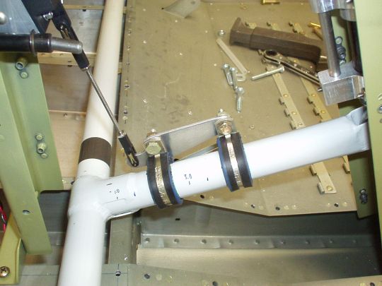
I fabricated a plate from 0.090" aluminum (0.100" would have
been ideal to match the width of the clevis) and connected it to the
torque tube lever arm using two cushioned clamps 2" apart (see
photo below). The bolt hole of the cushioned clamp
(MS21919-WDG16, 1" tube diameter) is laterally offset 1"
from the center of the tube, which is 1" above the center of the
tube in this mounting orientation. So the attachment point for
the push rod would need to be 1" below the bolt holes to line up
with the center line of the tube, or in this case only 0.5" below
the bolt holes to be 10° above the center line of the tube at a
radius of 1.5". In the longitudinal dimention, I placed the
bolt holes 2" apart as stated above, and the hole for the clevis
attachment 0.75" aft of the aft bolt hole.
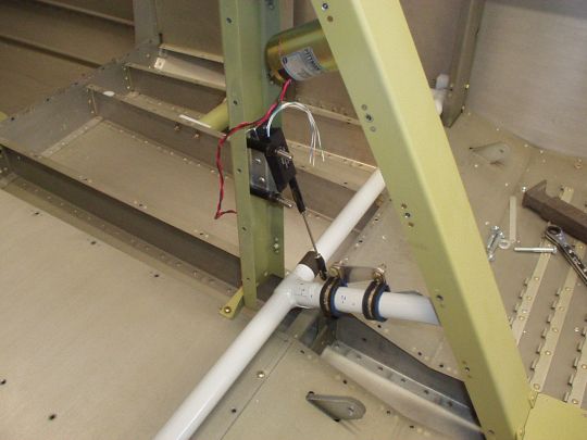
I used two pieces of aluminum angle to make a sort of "Z"
bracket with a 20° angle to mount the position sensor to the F-785A
channel (see photo below). I meant to use three rivets to
connect the two pieces of angle to each other, but as I discovered
just a little too late, the hole on the narrow side had enough room
around it to meet edge distance requirements, but not not enough room
to get any known riveting tool in there. So I enlarged the hole
to #29 and used a 6-32 x 3/8" stainless steel screw and nut
instead.
 |
|
|