|
  

Flaps Actuator
Running Total Hours:
0.0
 | 2006.01.15:
(2.0) Reamed out the bolt holes
in the torque tube weldment. Drilled the bushing blocks.
While the bushing blocks should be "match drilled" to the
pre-punched holes in the bulkhead, this is not practical as the
bulkhead is already installed. I drilled the the bushings from
measurements, which came out perfect for one and not quite for the
other. I think part of the reason was that I was just holding
the blocks down to the drill press base, and the drill tends to grab
the plastic. I'll order a replacement part and go pick up a
drill press vise. |
| 2006.01.19:
(1.0) Refer to DWG 20.
Electric flaps were an option on the RV-6(A) and are standard on the
RV-7(A). Van's design of the actuation mechanism for the
electric flaps is, in principle, simple and effective.
Unfortunately, there are a couple of serious flaws in the details of
the design that I find unacceptable. Flaws that are readily
apparent on the plans. Flaws that could have easily been
corrected, but for whatever reason were not. Annoying...
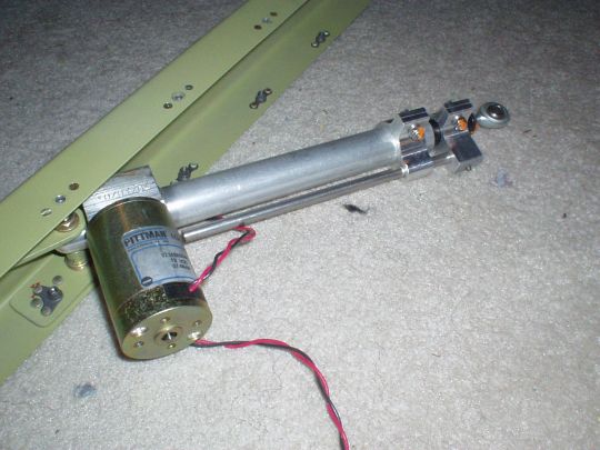
1. The motor assembly has a gearbox with a jackscrew (or similar)
mechanism used to extend or retract the actuator arm. But when I
bench tested it I found that the actuator shaft doesn't extend or
retract. It just spins. If I hold the actuator shaft to
keep it from spinning (with considerable torque), then it extends or
retracts. An query to the Yahoo group confirmed that my
actuator is not defective, that's just how it is. A good design
would have a built-in mechanism to keep it from rotating, but instead
Van's design relies on a Mickey Mouse "safety wire" through
the actuator shaft and the clevis bolt. The problem with this is
that the "safety wire" is not really a safety wire at all,
in that it relies on its overall rigidity, not just in direct tension,
to keep the actuator from spinning. Furthermore, on every cycle
of the flaps, the actuator will exert a torque on the wire in either
direction. After who knows how many cycles, the wire will work
harden, will fatigue, and eventually fail. Then the actuator
will exert a torque that will only be opposed by the jam nut on the
rod end bearing, which will eventually work loose and the rod end will
unscrew from the actuator. Not cool.
I decided to correct this by adding a retention mechanism to the
actuator itself to prevent the shaft from rotating. After
considering several design ideas, consulting with Vay, Annie, and the
Yahoo group, I decided to go with a simple design using a couple of
collars with an offset rod and a guide hole. This design concept
was used successfully by RV builder Lorne Heise, and in fact I decided
to shamelessly produce a very similar design to his. I drew up a
design, and now it's up to Annie (an ME/BE grad student and machine
shop TA) to go make me one. Thanks Annie!
2. The actuator shaft and the (weldment) torque tube arm don't line up
with each other! Conveniently, there is no single view on the
plans that shows both. But studying the plans still reveals the
problem. The motor/actuator assembly is asymmetric, with the
motor hanging to the right of center and the actuator shaft to the
left of center. The arm on the torque tube weldment though is
perfectly centered, yet the two are expected to meet up. The
"nominal" misalignment appears to be about 5/16".
Van's could have fixed this problem by simply welding the arm on the
torque tube 5/16" left of center. Why they didn't, who
knows. Presumably this is a relic from the RV-6(A) manual
flaps. But come on, retooling a welding jig is not that big a
deal, and in this case would make the design "correct" and
save a lot of trouble for us builders.
Some builders have reported "fixing" this problem by
mounting the actuator at a slight angle away from vertical.
Doing this appears to solve the problem in one (and only one) flap
position, but now the actuator and the arm will move in slightly
different planes, and therefore will try to twist the support
structure. There may be enough slop and flex in the system to
get away with this, but that's just plain kludgey.
Carefully studying the dimensions, it looks like I can compensate for
some of the misalignment in two places: 1. mount the actuator as far
to the right as it can go without causing interference, and 2. connect
the rod end bearing to the far left end of the clevis, with all the
shimming washers on the right. Looks like between those two I
can make up just over half the misalignment. Will this be enough
to get me home? |
| 2006.02.08:
(2.0) Making brackets, etc. |
| 2006.02.10:
(8.0) Working on the support
structure (did prep, prime, assembly...). |
| 2006.02.21: (1.0)
Received another bushing from Van's and drilled it using my new
Craftsman drill press vise. Came out perfect.
Interestingly, this bushing as delivered by Van's was machined to
dimensions slightly larger than nominal, and the edges have
significant burrs. The others were dead on dimensions and neatly
finished. Not really a problem, but Van's occasional sloppiness
in manufacturing/QA doesn't give me the warm fuzzies. |
| 2006.02.24: (2.0)
And on the next problem... With the bushing blocks pushed onto
the weldment as far as they go, the distance between them is
3/16" wider than it needs to be to fit the fuselage. The
tube wasn't bottoming out against the back of the bushing, but rather
the welds connecting the arms to the tube were the limiting
factor. After studying the measurements, comparing to other
builders' measurements, and consulting with Van's, it became apparent
that the basic measurements are all correct, but the welds were sloppy
and the fillets just extended too far outboard. Van's suggested
drilling the blocks off center to space them out further, but I didn't
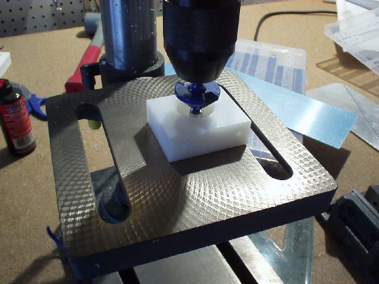
like reducing the edge margin there. My solution (which Van's
approved) was to bevel out just enough of the bushings to make
clearance for weld fillets. I used a 45º router bit.
 |
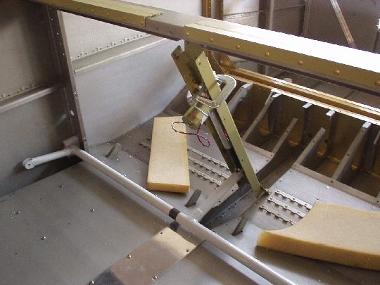
| 2006.02.25: (3.0)
With the weldment and outboard bushings now in place, I fitted the
flap actuator motor. While I was already anticipating a
misalignment (see 2006.01.19 problem 2), I now found that it's
1/8" worse because the actuator arm is welded to the tube
not quite square. Of course, it's tilted to the right, to make
the misalignment problem worse instead of better. Anyway, by
offsetting every connection as described above (2006.01.19), and
mounting the motor at a slight angle away from vertical, I got things
to fit. Despite the slight angle, actuation is reasonably
smooth. I'll have to wait until the whole structure is put
together (side covers and all) to see if there's any significant
flexing.
 |
| 2006.02.26: (0.5)
Drilled the center bushing block to the floor. |
| 2006.03.03: (0.5)
Of the two holes drilled into the floor structure for the center
bushing blocks, only the aft one can be fitted with a standard nut
plate. The forward one cannot because of how the baggage floor
rib and the bulkhead overlap at the joint. I fabricated a little
plate that a nut plate can be attached to at a 45 deg angle, and is
long enough that it can be riveted to the floor rib past the lap joint
with the bulkhead. Better explained with a couple of pictures: |
| 2006.03.15: (1.5)
Drilled the cover panels to the support channels and installed nut
plates in the channels. |
| 2006.03.17: (1.0)
Cut out a clearance in the left cover panel for the bolt head.
Deburred both cover panels. |
| 2006.03.19: (2.0)
The bolts are spaced pretty far apart per the plans, which allows the
edges of the cover panels quite a bit of play between the
screws. The loose edge looks bad, and could easily get caught on
something, and could easily vibrate and make noise. So I decided
to double the number of screws attaching the cover panels to the
support channels, reducing the screw spacing from about 6" to
about 3". Drilled, installed nut plates, etc.
Note that I positioned one of the screws just above the cutout for the
bolt. This took some careful planning in precisely positioning
the screw hole, as well as the nut plate rivets, as to maintain edge
distance and not compromise the strength of the reinforcement plate on
the inside of the channel.
Ideally I would have liked to add another screw just below the cutout
for the bolt, but adding a nut plate there is likely to interfere with
the flap motor, so the one on top will have to be good enough. |
| 2006.8.20: (0.0)
I finally got around to putting together and testing my contraption
for keeping the actuator jackscrew from free-spinning. Well,
this first prototype didn't operate very smoothly. The problem
was that the aluminum rod sliding through a hole in the aluminum
collar just tended to bind and grind. I concluded that aluminum
is just too soft or produces too much friction in this kind of
interface, with that much force applied. So I came up with an
ECO ("Engineering Change Order", industry jargon for a fix
to make it work):
1. I replaced the aluminum rod with a stainless steel rod.
Stainless steel is much harder than aluminum, and tends to hold a
smoother surface.
2. On the collar side, I added a brass sleeve that will act as the
slide bushing surface instead of the aluminum. I found some
brass tube that had an outer diameter of 9/32" and wall thickness
of 0.014", yielding an inner diameter of 0.25325" (just
0.00325" greater than the 0.25" rod). I drilled out
the hole in the aluminum collar to 9/32", which actually made for
an interference fit as is. The brass tube would not slide
through it with hand force. Perfect! So I put the brass
tube in the freezer and the aluminum collar in the oven at 200ºF for
half an hour. With that temperature differential I was able to
push the tube in about a millimeter by hand, and then tapped it in the
rest of the way with a mallet. I think a couple of extra taps
with the mallet also served to compess the tube longitudenally and
expand it radially ever so slightly, for a tighter fit. In any
case, they were never coming apart again, especially after a minute
when their temperatures fully equalized. I then cut off the long
tube end and filed everything down flush, leaving a perfect
cylindrical insert. Note that I bought the brass tubing at
Marshall's Industrial Hardware, but it's also available at any hobby
shop in those displays of small metal stock. It is "K&S
Engineering stock #132".
With that ECO complete, everything operates smooth as silk. So
stainless steel against brass really does make a much better slide
bushing interface than aluminum against aluminum.
 |
|
|