| 2006.04.14:
(3.5) The optional electric
aileron trim comes as another little kit that includes a Ray Allen
servo and installation materials. Unlike the elevator trim,
which uses a servo to control an aerodynamic trim tab on the elevator,
the aileron trim system provides bias using a servo that is
spring-coupled directly to the control column.
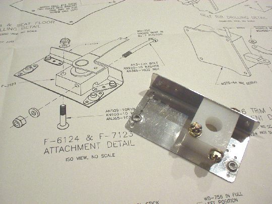
Let's get to work. Trimmed and fitted the bushing block and
bracket to each other and to the fuselage.
 |
| 2006.04.15:
(2.5) Trimmed, drilled, and
bent the bell crank weldment to its final shape. Edge-finished
the little linkage pieces. Next, I ran into two design elements
that I didn't like:
1. The geometry is such that the C-606 linkages that connect the
springs to the control column will experience rotational forces (i.e.
torque) any time the stick is not centered laterally. There's nothing
to oppose the rotational forces other than the friction/tightness of
the one bolt that connects the C-606 linkage to the control column
(that also connects the F-665 pushrod). So there's potential here for
the bolt to loosen and the linkage to start rotating. Or worse, the
bolt could eventually come completely loose and the F-665 pushrod
would disconnect from the control column. Not a very robust design,
and failure here could be catastrophic. I think the simple and
logical way to do this is to redesign the C-606 linkage so that it
connects to the control column through both bolts. That way the shear
strength of the bolts opposes rotation, rather than relying on
friction/tightness. I sent an email to Van's tech support. Let's see
what they say.
2. The servo mounts to the web of the seat rib right over a protruding
bead, preventing the servo from sitting flush. There's a comment
in the plans "allow servo motor to distort bead in seat
rib". We'll see how this works out, whether or not more
than just the bead will get deformed under tension. Pretty
cheesy. |
| 2006.04.22:
(1.0) Sprayed AKZO on the trim bracket
and linkages. |
| 2006.04.23:
(0.5) Riveted the nut plates to the
trim bracket and assembled with the bushing block. |
| 2006.04.25:
(1.5) Installed the trim bracket
assembly in the fuselage and used it to position the servo motor on
the seat rib (clamped in place). I found that I didn't have any
tool that could match-drill the servo mounting holes, because of the
cramped space. The right angle drill is basically the right
solution, except that the threaded drill bits I have are too short to
clear the servo motor. Will buy some longer bits. |
| 2006.04.30:
(0.5) Match-drilled the mounting holes
for the servo using the angle drill and some 2-1/8" long bits
(#30, then #28 for 6-32 screws) from Avery. Piece of cake with
the right tools.
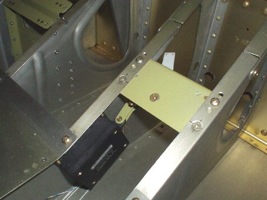 |
| 2008.12.10:
(0.0) Just catching up on some
documentation from a while back... With respect to the issue I
raised on 2006.04.15: As expected, Van's didn't show much
interest. That's ok. It's my airplane, so I corrected the
problem anyway.
[insert photo here] |