|
  

Magnetometer
Running Total Hours:
0.0
 | 2009.05.19: (0.0)
The magnetometer is a solid state device that can measure the magnetic
field in three dimensions, and is a key component of any EFIS
system. It is obviously used in determining the aircraft's
heading, but may also be used by the AHRS as an aiding input to the
attitude solution. While some EFIS systems may incorporate the
magnetometer in the main box, most EFIS systems today (including AFS,
Dynon, GRT, BMA) use a remote magnetometer module, such that it can be
mounted in another location that is sufficiently free of magnetic
interference, unlike the instrument panel. The magnetometer also
has to be mounted in the same orientation as the AHRS, in all three
axes, within fairly tight tolerances. [Theoretically, the
magnetometer could be mounted in any orientation, as long as the
orientation relative to the AHRS is known, and can therefore be
corrected for numerically. But most EFIS vendors don't seem to
support that option.]
I'm currently planning on an EFIS from Advanced
Flight Systems, so details of the magnetometer installation that
are vendor-specific are based on Advanced Flight Systems'
requirements.
MAGNETOMETER LOCATION
The number of suitable locations for the magnetometer are actually
fairly limited due to the need for it to be free of magnetic
interference. AFS generally recommends that the magnetometer be
located at least 24 inches away from any ferrous object, any moving
metal object (ferrous or not), and any wires carrying any significant
current. Most other EFIS vendors have similar recommendations.
There is actually no location on the RV-7A that strictly meets that
criteria. But the most suitable location, and one that has
seemingly worked well for others, is on the top forward side of the
F-707 bulkhead (one bay aft of the baggage compartment). At this
location, the magnetometer is sufficiently far away from the elevator
bellcrank and pushrods, autopilot pitch servo, steel rudder cables,
the wire harness running along the bottom to the aft fuselage, and the
baggage compartment (who knows what someone might put there???).
However, it is only about 8 inches away from the steel cables that
secure the pilot and passenger shoulder harnesses to the longerons in
the aft fuselage. These are
ferrous (steel), and worse, they can move around somewhat when they are
slack. But the good news is that we can easily test and find
that they have little effect. Measuring with a mechanical
compass as well as with a digital compass (both mountaineering equipment) I
see less than ±1° of deviation with the cable 8 inches away from the
compass. But there is definitely an effect. At 1 to 2
inches away, the cable will cause the compass to swing as much as
5°. And the clevises at the ends of the cable can swing the
compass a full 90°, but fortunately these will always be far from the
magnetometers. Still, I may experiment and see if I can degauss
the cables to get rid of as much magnetic bias as possible.
MAGNETOMETER MOUNT
So I've picked the location, but there are still some challenges to
mounting the magnetometer. It has to be aligned with the AHRS in
all three axes within 0.2° (sounds like people are actually getting
away with much looser tolerances, but 0.2° is what AFS specifies and
that's what I intend to meet). In the AFS EFIS, the AHRS is inside the main box
that goes in the instrument panel. And in the RV-7A, the
instument panel is not perfectly vertical but rather tilted forward about
7.7° in pitch. So the magnetometer mount must be tilted in pitch by the
same amount. The other two axes should match those of the
airplane. With careful measurements and a digital level, I think
I can meet the 0.2° spec.
The tricky part here is that there is no really good structure to
attach a mount to. The F-707 bulkhead itself would be the
obvious choice, but the way it's put together, it's actually not so
great. It is a relatively floppy structure with easily a few
degrees worth of flex. Even just sitting there now, it naturally
deviates away from its proper plane (partly due to its flimsy design,
partly due to less than exacting workmanship by the QB factory).
And the bulkhead has a stiffener bead protruding forward, getting in
the way of attaching any flat flange to the forward side of the
web. Just plain unfriendly.
Also complicating matters, I want to make provisions for mounting two
magnetometers. To minimize interference, they should also be
spaced apart from each other as much as possible. Rob Hickman at
AFS has found in his RV-10 that about 10 inches apart is sufficient,
so that's about what I'm shooting for.
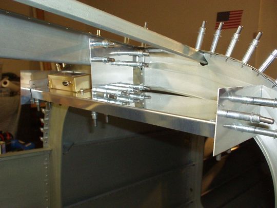
I sketched out a few different designs for the mount, and here's what I
finally settled on. The mount will be an 18 inch wide tray, with
three brackets attaching it to the fuselage. One bracket in the
center attaching it to the F-787 stringer, and one bracket on each
side attaching it to the F-707 bulkhead. The center attachment
to the stringer provides a very stable reference for the pitch
axis. The side attachments to the bulkhead provide a
stable reference for the other two axes due to the 18 inch distance
between them. The tray itself will have 90° flanges to make it
very stiff longitudinally. It'll still be able to twist a little
with the bulkhead, which I think to a degree is actually desireable, so that
the mount doesn't induce excessive stresses on the bulkhead as the
aircraft twists under load. Any twist
under normal conditions should be negligible for the orientation of
the magnetometers. |
| 2009.06.27: (0.0)
I've received the Advanced
Flight Systems magnetometer (AFS p/n 8350-0480) from SteinAir.
Note that this magnetometer is actually made by Crossbow,
and carries a Crossbow label specifying "Model: CRM300CA-100,
Part No: 8350-0480-03, Serial No: 0901000362".
My fabrication of the mount is well under way. Its main
structure is fitted in place, and only some final trimming
remains. I drilled mounting holes for two magnetometers, spaced
laterally approximately 11.25 inches apart center-to-center.
[Note that the attachment hardware shown in the following photos is
stainless steel, but this is just temporary. Non-ferrous
hardware will be used in the final installation.]

Note that Dynon's magnetometer, incidentally, has exactly the same
footprint as AFS's, so my mount as-is will accomodate either.
And while I'm at it, I may drill mounting holes for other
manufacturers' magnetometers as well, since it's easy to do at this
stage. |
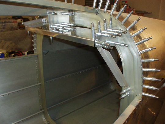
| 2009.07.07: (0.0)
As I expected, this mounting tray design still has a little bit of
freedom to twist, i.e. the left side can pitch up a little while the
right side pitches down a little, or vice versa. Not a lot, but
enough that I was a bit worried about it flexing unevenly under heavy
G-loads (since it's asymmetric), or resonating with normal vibration
of the airframe. So I decided to stiffen it up by adding a
member from the forward left corner of the tray to the
bulkhead-longeron intersection underneath, thereby creating an
excellent truss. Sure enough, this stiffened it right up.
I'm not doing the same on the right side because 1. it is unnecessary,
and 2. again, I want to leave enough flexibility so that it doesn't
impose any hard stresses on the bulkhead as the airframe naturally
flexes and twists. [An alternate design could have had trusses
on both sides and eliminated the center support. That would
probably work reasonably well. But the center support is still a
stiffer reference for pitch angle, and it also made it much easier to
set pitch angle first, without worrying about other two axes, so it
made for a more manageable construction sequence.]
I did the final trimming, removing excess material, rounding over
corners, etc. And treated all the parts with alodine, followed
by AKZO primer. Now all that remains is to rivet it, but I'll
wait on that for now so it's not in my way. |
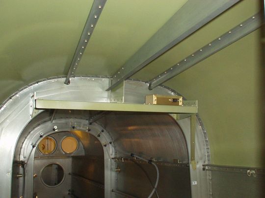
| 2011.04.21: (0.0)
Installed. The top skin is riveted, as is the magnetometer
shelf, and the magnetometer is mounted in its place. Note that
to secure the magnetometer to the shelf I used mounting hardware (#6
screws, nuts, washers) made of aluminum, for magnetic
considerations. I found this aluminum hardware at Marshalls (not
cheap of course...). Had to shorten the screws. And also
gave all the hardware an alodine treatment for good measure. And
finally, used some loctite to make sure everything stays put.
 |
|
|