|
  

Horizontal Stabilizer Construction
Start: 2004.01.18, Completion:
2004.07.18, Hours: 123.5
 |
2004.01.18: (4.0)
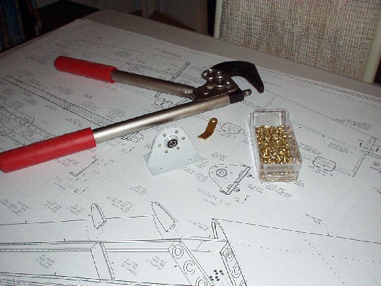
Construction work begins. Smoothed out the edges of the rear spar reinforcement bars
(HS-609PP). The first one took a few iterations of trial and
error, as this is still a learning curve. I was initially not aggressive
enough with the file, and ended up obliterating an entire small scotchbrite
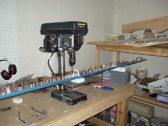
wheel (1"x1" 7A-medium mounted in a drill press) to finish the job.
The second bar went much more efficiently with generous use of the
file followed by a couple of quick passes on another scotchbrite wheel
(2"x3/4" 7A-medium). The reinforcement bars lay flat
in proper alignment in the rear spar channels (HS-603PP). |
|
2004.01.19: (2.0)
Rounded the ends of the rear spar reinforcement bars (HS-609PP) using a file,
then scotchbrite wheel. Started smoothing the remaining surfaces
with a maroon scotchbrite pad, but found that it didn't have enough
bite to remove some of the pits and scratches on the surface of the
bars. |
|
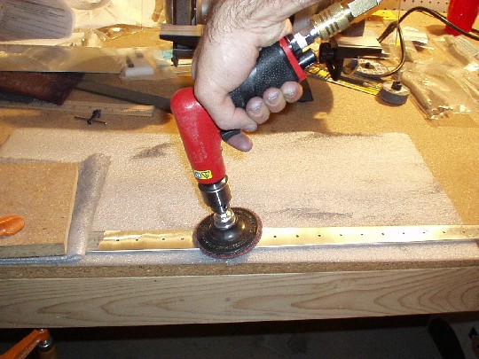
2004.01.21: (1.5)
Working on the surface finish of the rear spar reinforcement bars (HS-609PP) using
3M roloc discs mounted in the drill press. The discs are doing
their job, but it seems that I'm removing a substantial amount of
material and still not eliminating the worst of the surface
defects. Will consult the RV email groups and Van's support. |
| 2004.01.26: (0.5)
Marked the end radius and taper on HS-714. |
| 2004.01.26: (0.5)
Back to the rear spar. Deburred the HS-411 elevator bearing
assembly components before riveting. |
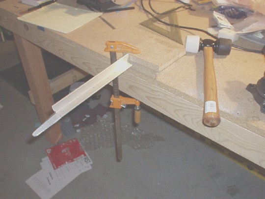
| 2004.01.31: (5.5)
Bent the outboard sections of HS-710 and HS-714 six degrees. To
do each bend, placed the outboard section between two pieces of
particle board with a rounded edge for the bend radius. Since
the free end (center section of the part) still had the right-angle
cross-section, it was rigid enough to push down by hand without
distorting it. This actually worked better than the prescribed
mallet, which tended to bounce.
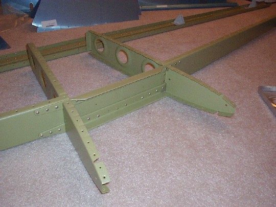
Trimmed the inboard section of the front spar channels (HS-702).
Straightened out the extra flange with a hand seamer before cutting it
free of the web. Otherwise, the flange bend would have been
difficult to eliminate without removing more of the web. There's
still some fine finishing to do. |
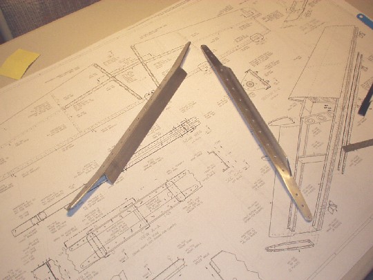
| 2004.02.02: (2.0)
Cleaned up the trimming of front spar channels HS-702 and made the six
degree bends. Test fit the front spar channels with the HS-710
and HS-714 angles to verify that all the bends match up nicely. |
| 2004.02.03: (2.0)
Practiced dimpling and countersinking on some scrap. Just
learning how to use and adjust the tools properly, no actual progress
on the airplane. |
| 2004.02.04: (1.0)
Countersunk the four center holes in the front spar for flush
rivets. Dimpled the HS-702 spar channels and machine-countersunk
the HS-710 and HS-714 angles. After a couple of single click
adjustments on the countersink cage, the fit is just about
perfect. But it just occurred to me that after buffing out some
minor scratches from the angle stock, the holes will probably have to
be countersunk a little more. Should have done the finishing
work first. |
| 2004.02.05: (1.5)
Edge and surface finishing the HS-710 and HS-714 angles. Had to
first use a file to level the outboard web regions where the flange
has been machined away. Then used the same set of techniques as
for the rear spar reinforcement bars (see 2004.1.23). |
| 2004.02.06: (2.0)
Finished buffing out the HS-710 and HS-714 angles.
Re-countersunk the center rivet holes to compensate for the slight
amount of removed surface material. Now a perfect fit again to
the dimples in HS-702.
Started trimming the HS-404 forward root ribs. Drilled the
inner radii, then made the straight cuts using a little Dremel cutoff
wheel in the pneumatic drill.
 |
| 2004.02.08: (1.5)
Done trimming the HS-404 ribs using files. Started
edge-finishing. |
| 2004.02.09: (1.5)
Done edge-finishing the left side HS-404 rib. |
| 2004.02.10: (1.5)
Done edge-finishing the right side HS-404 rib. Started
edge-finishing the HS-706 ribs. |
| 2004.02.13: (1.0)
Edge finishing the HS-706, HS-707, HS-708, and HS-405 ribs. |
| 2004.02.14: (2.5)
Edge finishing the HS-706, HS-707, HS-708, and HS-405 ribs. |
| 2004.02.17: (1.0)
Noticed that the HS-706 tip ribs have
substantial defects on the aft flange. There are what look like
cracks or grooves on the forward (bent in) face, and slight
protrusions on the opposite (aft) face. The defects on both ribs are
identical. Probably some debris was between the flange and the
form when the parts were pressed. Time to talk to Van's. |
| 2004.02.20: Spoke
with Tom Green (president of Van's) about the HS-706 defects. He requested
that I send him the parts for inspection. Unfortunately, I
forgot to take photos before sending away the parts. |
| 2004.02.23: (1.5)
Done edge finishing the ribs, except for HS-706 which are on their way
back to Van's. |
| 2004.03.3:
Called Tom at Van's to follow up on the HS-706 issue, and to discuss
another two defective parts that I've found after closer
inspection. He said he had sent me some new HS-706 parts,
although he insisted the "markings" were benign and told me
to expect the same markings on the new parts. He said the
markings were actually part of a serial number embossed on the press
dye. When I came home in the evening, a UPS package was waiting
at my door. While the same type of markings were present on the
new parts, they were not nearly as deep as those on the original
parts, and I'm satisfied that these are superficial and could easily
be buffed out.
The other two parts we discussed are one of the HS-702 front spar
channels (the right), and the VS-707 rib. The HS-702 had
shear-like defects on the edges of two flanges, extending about
1/8" into the flange. I should be able to remove enough
material to eliminate the defect and still maintain proper edge
margin. The VS-707 has sharp punch-like deformations on both of
the small flanges that go inside the front spar channel. In this
instance, there is no way to remove the defect without significantly
weakening the flange. After (and before) seeing some photos, Tom
insisted that these defects also are nothing to worry about, and that
I should just use the parts as is. I'm still skeptical and plan
on getting a second opinion.
 |
| 2004.03.6: (4.0)
Edge finishing the new HS-706 ribs and left HS spar channels. |
| 2004.03.7: (2.0)
Done edge finishing the left HS components. Straightened out all
HS ribs except for the center ribs by fluting.
 |
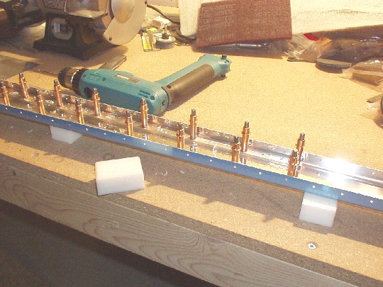
| 2004.03.9: (3.0)
Adjusted the fit and match drilled the left HS spar skeleton (spars
and ribs). Used the HS-601PP skin for alignment. Clecoed
together the entire left HS including skin. Fluted the HS-404
and HS-405 root ribs.
 |
| 2004.03.11: (2.0)
Drilled through the left HS-601PP skin to the HS-405 rib and inboard
section of the HS-702 front spar channel. The most forward hole
of the HS-405 flanges (where all three HS-601, HS-405, and HS-702 are
riveted together) does not meet normal edge distance requirements,
with an edge distance of only about one hole diameter. This
issue has been discussed on the message boards, and apparently Van's
gives it the standard "don't worry about it". In this
particular instance, that's probably the right answer.
Clecoed on the HS-714 and HS-710 angles. There may be a slight
interference between the HS-714 angle and the flange of the HS-404
rib, depending on how deep into the HS the rib is positioned. I
may just trim the rib flange slightly so I can position it where I
think it should go. Will consult with other builders.
 |
| 2004.03.15: (0.5)
Trimmed the bottom flange of HS-404 slightly to prevent interference
with HS-714. |
| 2004.03.16: (0.5)
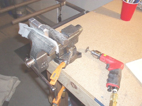
Drilled the four holes between HS-405, HS-702, HS-710, HS-714, and
HS-404. Used a right angle drill attachment with a six inch
extension shaft to drill the holes as perpendicular as possible. |
| 2004.03.18: (2.5)
Final drilled all remaining holes through skin to skeleton of the left
HS. |
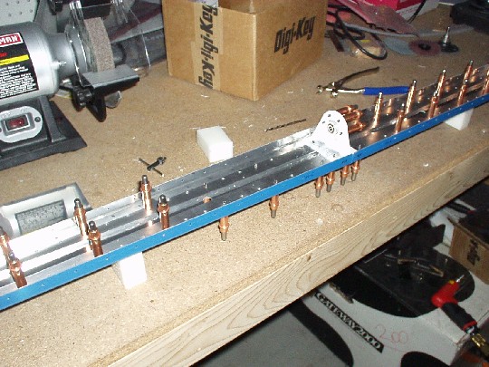
| 2004.03.22: (3.0)
Drilled the outboard holes through HS-710 and HS-714, then onto the
right half of the horizontal stabilizer. Drilled skeleton,
clecoed on the skin, and drilled HS-405 aft inboard rib and HS-702
front spar. Ready to drill through the rest of the skin. |
| 2004.03.24: (2.0)
Final drilled all remaining holes through skin to skeleton of the
right HS. |
| 2004.03.25: (0.5)
Removed the skin and drilled the outboard holes through HS-710 and
HS-714. |
| 2004.03.28: (2.0)
Disassembled the HS and deburred the holes. |
| 2004.04.03: (1.0)
Dimpled the left HS ribs using a tank dimple die, which is slightly
deeper than a standard die. This allows the dimple in the skin
to be fully seated within the dimple in the substructure. A tip
I picked up from other builders on the message boards. |
| 2004.04.06: (1.0)
Dimpled the right HS ribs. |
| 2004.04.11: (2.5)
Dimpled the spar channels using a tank dimple die. Edge finished
and dimpled the right HS skin using a standard dimple die.
Noticed that dimpling using the C-frame setup produced better results
than using the squeezer, with less distortion to the skin around the
dimple. So I used the C-frame to dimple all the holes in the
skin, even those along the edges that would be accessible with a
squeezer. Stacked some packing foam to support the skin on
either side of the C-frame at the height of the dimple die. |
| 2004.04.16: (1.0)
Dimpled the bottom side of the left HS skin. |
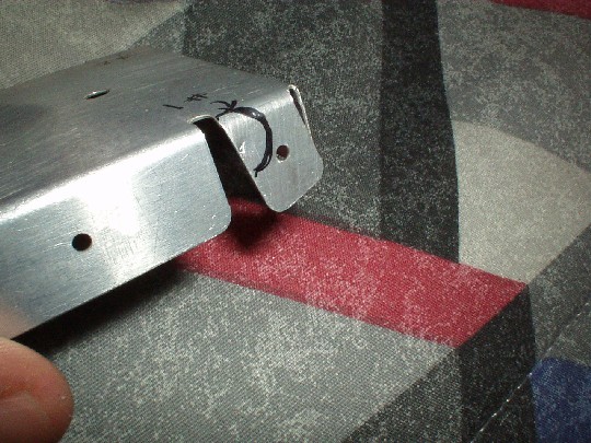
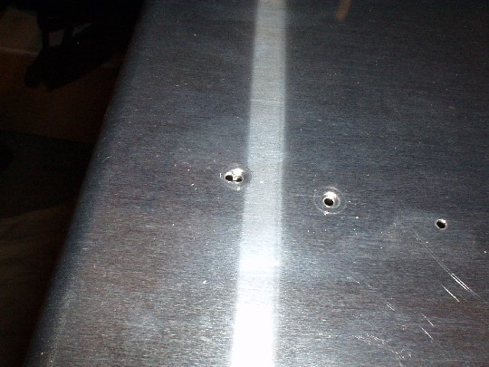
| 2004.04.17:
Help! I screwed up... Dimpling the top side of the left HS
skin, I made what I now know is called "the dreaded dimple
eight". It's what happens in a moment of inattention when
you let the dimple die slip out of the hole right before smacking it
with the hammer. It punches another perfect little hole (and
dimple) right next to the hole where the dimple should have
gone. Notice the two adjacent holes look just like the number
"8". This happened on the most forward hole in the row
that connects the skin to the HS-707 rib, which is somewhat hard to
get to with the C-frame (takes some flexing of the skin).
I was able to flatten out the misplaced dimple using a flush set in
the C-frame, but was still left with the "8". I
concluded that I could clean up the hole so that it wouldn't create a
stress concentration, so long as I didn't put a rivet through
it. So I was left with the question of whether the skin was
still usable or not. The best option I could see for salvaging
the skin was to make a new rivet hole a little forward of the damaged
hole, as there was sufficient area left on the HS-707 flange to do
this and still meet edge margin requirements. However, the new
rivet hole would be even more difficult to get to, both for dimpling
and driving the rivet. The other option would be to buy a
new skin, but I was concerned about fit issues since all the
understructure has been match-drilled to the original skin.
Discussing this with Van's, I was assured that the pre-punched skins
match closely enough to be interchangeable at this stage. I
therefore decided to opt for a new skin. |
| 2004.05.20: (1.0)
Went to work on a shiny new HS-601PP skin. [I've been out of
action for a month because of my day job, not waiting for the new
skin. Van's took just a week to deliver.] Final drilled
and deburred the holes on the new skin. |
| 2004.05.22: (3.0)
Edge-finished the new skin, then dimpled it without incident. |
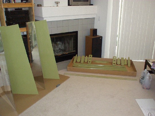
| 2004.05.23: (4.0)
First try at aluminum surface treatment for corrosion proofing
(commonly referred to as priming, incorrectly in my opinion since no
additional topcoat will be applied). The process I chose is as
follows: 1. clean with acetone, 2. alumiprep 33 etch while scrubbing
with maroon scotchbrite, 3. alodine 1201 conversion treatment, 4. AKZO
463-12-8 interior epoxy primer. RV-7 builder Dan Checkoway
documented his experience with basically the same process, and I
borrowed some of his
techniques.
Did a trial run on a piece
of scrap to debug the process, then did the five ribs of the left
HS. The surface prep and alodine are a no-brainer. Using a
zip-lock bag for the alodine worked great (thanks Dan!). I found
spraying the AKZO to be a little more tricky. The first attempt
on a piece of scrap resulted in a very heavy and uneven coat.
After adjusting my technique, I was reasonably satisfied with how the
ribs came out. The coat thickness was still not completely even,
but all areas had what I think is a an acceptable coat thickness. |
| 2004.05.25: (4.0)
Another evening session of corrosion proofing. Getting improved
results and working more efficiently, but this is still a very time
consuming process... |
| 2004.05.29: (4.0)
More corrosion proofing. Common sense perhaps, but I found that
it really is much easier to spray an even coat in daylight. I
was very pleased with how the parts came out from this session. |
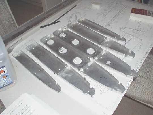
| 2004.06.05: (6.0)
Finished corrosion proofing the last of the HS components - the right
side ribs and both skins. I chose to use the same process on the
interior of the skins as I did on all the interior components.
But the exterior side of the skins should stay pristine for whatever
exterior paint system I'll end up using when the time comes.
To prevent alumiprep from getting on the exterior, I put blue 3M
painter's tape on the exterior along all the rivet lines. When
done scrubbing with scotchbrite + alumiprep, I quickly removed the
tape and washed the entire skin. I then applied tape again,
brushed on the alodine for 3 minutes, quickly removed the tape again
and washed the skins. The tape may have been unnecessary for
both these steps, since the exterior alclad would have probably not
reacted much with the chemicals (the exterior didn't get the
scotchbrite, so the alclad is all still there), but masking it gave me
the warm fuzzies. I went even further for the AKZO.
I masked the exterior along all the edges and rivet lines with 3M
tape, then masked pretty much all the exterior surface with paper to
prevent overspray from making its way there. Doing this actually
didn't take too long, but it turned out to be completely
unnecessary. After spraying, I inspected the exterior side of
the masking tape and paper and found no evidence of overspray.
Still, again, warm fuzzies. Anyway, nice to be done with all
these nasty chemicals for a while. Time to start putting this
thing together. |
| 2004.06.06: (4.0)
Clecoed up the left HS for a test fit, just to make sure there are no
issues with the replacement skin. Everything mated up perfectly,
tight and straight. Gotta love CNC.
Now finally to some assembly work. Riveted the rear spar using
hand squeezers. As the manual says, squeezing 1/8" rivets
takes a bit of grunt. Not too bad on the first few, but after a
hundred or so I was pretty worn out. Still, what's nice about
the squeezers is that you can work late at night, solo, and without
making a sound (other than the occasional grunt). |
| 2004.06.07: (1.5)
Riveted up the forward spar and inboard ribs, again using the hand
squeezer.
 |
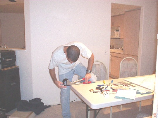
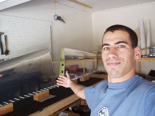
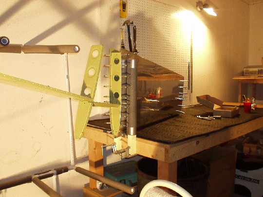
| 2004.06.12: (8.0)
Riveting the HS-707 nose rib to the left HS skin. Opted for all
solid rivets, no problem at all. Found that with a little practice,
driving and bucking solo is actually not very difficult. For
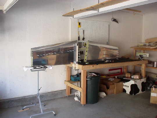
riveting the skin to the forward spar I fashioned a crude jig consisting of two padded vertical posts clamped
to the edge of the workbench, just to stand the HS up on its leading
edge.
 |
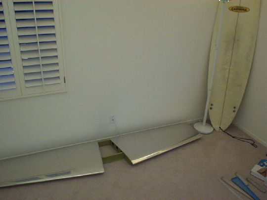
| 2004.06.12: (2.0)
Riveted the HS-707 nose rib to the right skin. Clecoed the right
HS skin to the front spar, currently all standing up on the trailing
edge for support. Will have to come up with a support jig. |
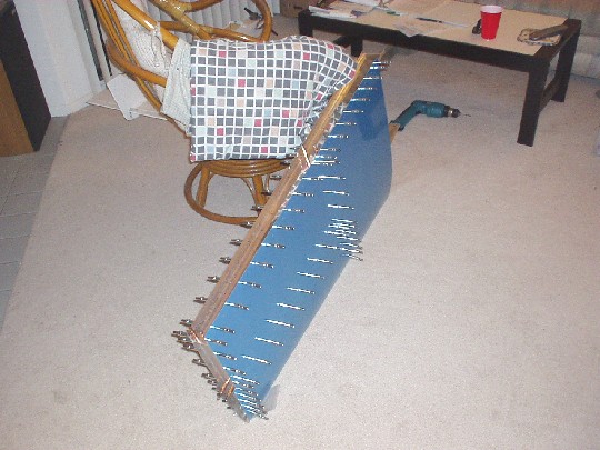
| 2004.06.19: (1.0)
Vay had a good idea to stand the HS up on its trailing edge, hang it
off the edge of the table and put up another support at outboard
end. An adjustable height pedestal from Home Depot did the
trick. This leaves the HS "box" open to buck from
underneath. |
|
|