|
  

Firewall Prep
 |
2010.12.20: (0.0)
This page will document work performed on the firewall *before* permanently installing the engine mount. The idea is to do as much firewall work as possible before permanently installing the engine mount (and engine) while access is good. The primary limitation is that the firewall forward drawings from Van's are not quite reliable due to many possible variations in engine configurations, and so the locations of some firewall penetrations and other installations can't be easily determined until after the engine is hung.
Parking brake valve
I installed the parking brake valve a while back at the the location Van's suggests for the F-6122-1 brake line support bracket shown on DWG 36A. This location had pre-punched holes in the firewall, and works well except that installation isn't supported directly by any stiffeners, just the thin firewall material. What we have is effectively a large mass suspended in the middle of a loose drum head... not so good. I think this will experience major "oil-canning", which will both produce cockpit noise as well as potentially cause fatigue failure of
the stainless steel firewall or the aluminum brake lines over time. I plan on installing an additional stiffener that will anchor the parking brake valve.
Main battery
I fabricated and fitted the main battery box to the firewall a while back. The battery box is positioned on the firewall in Van's suggested location per DWG 31A.
Master & starter relays
I'm installing the master and starter relays in Van's suggested locations under the battery box per DWG 31A. I did however fabricate a doubler that is shaped differently than the F-7127D shown on the plans. The F-7127D shown on the plans attaches to the firewall between the upright and diagonal stiffeners, but does not butt up against them except for in one corner. My doubler extends laterally all the way to the stiffeners to better support the mass of the relays and reduce oil-canning in the firewall.
Gascolator
I'm not installing a gascolator. Per Van's and other expert advice (Don Rivera at Airflow Performance), a gascolator is not necessary nor recommended for a fuel injected engine. Note that Canadian builders are required by their regs to install a gascolator regardless, but in the US there is no such requirement.
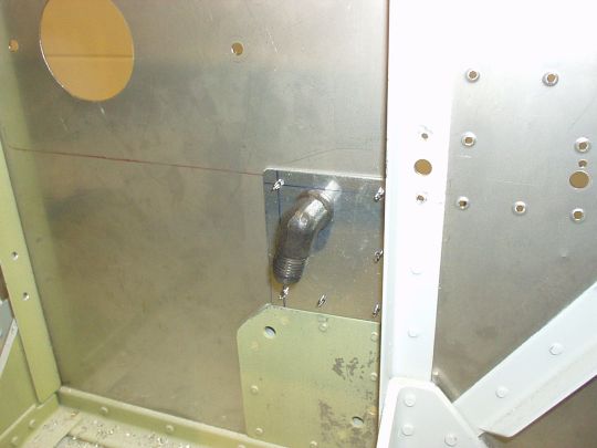
Fuel line penetration
My fuel line penetration is loosely based on Van's suggested installation for a fuel injected engine (i.e. no gascolator) per DWG OP-32, but with several differences as follows.
Firstly, DWG OP-32 calls for an AN833-6D bulkhead elbow fitting. I'm replacing it with an AN833-6, which is made of steel instead of aluminum. This better preserves the integrity of the firewall in case of engine fire.
Secondly, DWG OP-32 calls for a doubler on the forward (engine) side of the firewall which conflicts with the starter relay installation shown in DWG 31A. To resolve the conflict, I will install the doubler on the aft (cockpit) side of the firewall. I also find the aft side preferable because the doubler is aluminum, and so having it on the aft side makes it less vulnerable in case of engine fire. One drawback of having it on the aft side of the firewall however is that it cannot be riveted directly to the vertical stiffener. But I'm fitting the doubler such that it butts up against the vertical stiffener, as well as against the upper edge of the aux fuel pump doubler (low pressure aux pump for carburated engines, not used with fuel injection, but the QB folks already installed the doubler anyway and I'm not removing it). With this doubler geometry, there should be sufficient stiffness to keep vibration and oil-canning to a minimum, even without direct attachment to the vertical stiffener.
Thirdly, the penetration location called out on DWG OP-32 puts the fuel hose dangerously close to the output terminal of the starter relay. The possibility of these two coming in contact with each other is very very bad due to the potential for chafing of the fuel hose, and possibly even shorting the starter relay terminal to ground through the fuel hose to the tune of hundreds of amps, which is a recipe for igniting a catastrophic fire. Long story short, I moved the fuel line penetration inboard by 3/8 inch to provide adequate clearance from the starter relay.
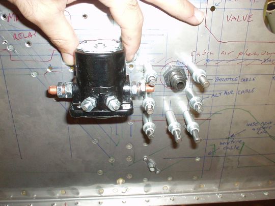
Control cable penetration method
Van's suggested method of fireproofing the control cable penetrations is shown on DWG OP-26. It consists of a pair of plastic snap bushings with proseal or RTV gooped over them. Seriously...
Instead, I'll be using a steel "eyeball" spherical grommet, which consists of a split steel ball (hollowed out from the back to keep it light) with a channel drilled in the middle for the cable. The sphere halves are clamped together and secured to the firewall with a pair of steel plates, and they clamp down on the control cable and hold it at any required angle up to about 45 degrees from the firewall. These spherical grommets are manufactured by Doubletree Products and/or Schultz Engineering (not sure about relationship between Doubletree and Schultz, but their products appear identical), and are sold by Spruce, Wick's, etc. for about $30 ea.
The channel in the middle of the spherical grommet has to match the diameter of the cable, and they are available in several common diameters. The cables sold by Van's are ACS A-800 (throttle), A-1760 (prop and mixture), and A-740 (alternate air). The A-740 is 0.188" diameter, and the spherical grommets are available in exactly that diameter. The bare A-800 and A-1760 cables are specified at 0.240" diameter on Spruce's web site, but note those sold by Van's have the optional polyolefin coating, and measure 0.266" in diameter. The closest diameter available in the spherical grommets is 0.260", which is what I'm planning to use. The polyolefin (rubbery plastic) is flexible and should be able to compress slightly.
Prop control cable penetration
I'm locating the prop control cable penetration at Van's suggested location per DWG 19. Note that I'm not using the MT governor from Van's, but rather a PCU5000X instead. But the installation geometry will nontheless be very similar.
The penetration is done using a steel spherical grommet with 0.260" channel diameter (see above).
Throttle, mixture & alternate air control cable penetrations
For the throttle, mixture, and alternate air control cable penetrations, I'm planning to deviate significantly from Van's suggested locations, and to wait until the engine is hung to select the exact locations.
Van's DWG 19 shows suggested locations for these penetrations to use for a carburated engine. The installation geometry of a vertical induction fuel injection servo is actually very similar to a carb, and the same control cable geometry would most likely work. But carb vs. FI aside, this suggested geometry is not so great to begin with. The suggested penetrations per DWG 19 are all in the lower right corner of the center tunnel. This is a very congested area, both on the engine side and on the cockpit side of the firewall. On the cockpit side we have the fuel line and the wiring harness running right through that area, and a goofy arrangement where the control cables would have to pass through the F-982E access plate (see DWG 34). On the forward side of the firewall, there is all the nose gear support structure, as well as the fuel line penetration. And even without all that, the suggested locations are too closely spaced to use spherical grommets, which require more room than Van's "fireproofed" snap bushings.
My plan is to locate these three cable penetrations within the firewall recess. Others report having done this in a few different variations. But since this is sparsely charted territory, I'll wait until the engine is hung to choose the final locations.
Cabin heat selector
I'm installing the cabin heat selector at Van's suggested location per DWG 19. Additional details also shown on DWG OP-26. Note that I'm using an aftermarket cabin heat selector (stainless steel rather than Van's aluminum), but the installation geometry is the same.
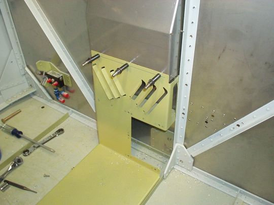
Firewall recess
The F-601K-1 firewall recess exists to provide clearance for the prop governor. The installation is straight forward per-plans, but it pays to look ahead here at several different drawings to do things the easy way before the firewall recess is riveted to the firewall. The basic installation is shown on DWG 19. Additional relevant drawings are as follows.
DWG 31A shows two holes that instead of rivets get enlarged to accomodate AN3 bolts to support the battery box.
DWG OP-27 shows two holes that instead of rivets get enlarged and #10 nut plates installed behind them for cushioned clamps to support the oil pressure hose.
DWG 34 shows two #8 nut plates that need to get installed in the firewall recess to secure the top of the F-782C center tunnel cover to the bottom of the firewall recess. Note that I also added a third nut plate in the middle to keep the thin aluminum F-782C from vibrating against the firewall recess.
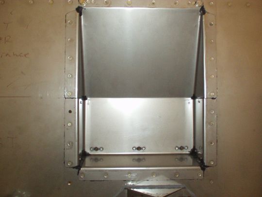
Finally, the firewall recess can be riveted to the firewall. A purpose-made sealant will be used to maintain a good fire barrier. This is PRC-DeSoto (A PPG Industries Company) Model 654 Semkit firewall sealing compound conforming to MIL-S-38249 AMEND. 3 NOTICE 2 TYPE I. This stuff is sold in mixer tubes like proseal. It is expensive ($45/tube), has a limited shelf life (1 yr), and requires hazmat shipping. Van's sells it, but it is dropped shipped directly from PPG (took a few weeks for it to arrive, no tracking info available from Van's, and can't directly contact PPG... pain in the a**). |
|
2010.12.27: (0.0)
Riveted some of the stiffeners and doublers for items described
above. John F helped with the riveting. |
|
2011.01.01: (0.0)
Stepping way off the trail now...
Ground power receptacle and relay
I'm adding a ground power receptacle, as described here.
This is rarely found on an RV, and the installation is of my own
design.
|
| 2011.03.07: (0.0)
Way behind on documentation... catching up on a few weeks'
worth.
Firewall recess
Firewall recess is in, riveted with help from John F. Used
PRC-DeSoto (PPG) P/S 700 firewall sealant (Van's p/n
MC-CS-1900). It meets spec MIL-S-38249 AMEND. 3 NOTICE 2 TYPE
1. This material is not easy to work with. It comes in a
2-part "semkit" package, and after mixing has only a 2 hour
working time. When working with it (immediately after mixing,
and at the recommended 70 deg F) is best described as a very viscous,
not very sticky, rubber, that is in a state somewhere between liquid
and solid. I used it under all the flanges of the firewall
recess such that it compresses and extrudes out during riveting, and
then I wiped off the excess. Also globbed some over the relief
holes in the corners of the firewall recess, as well as the gaps at
the bottom corners of the firewall. Ultimately the results were
pretty good -- looks like a good seal, and not terribly messy.
After curing for a couple of days, the compound is actually quite
hard. Much harder than typical rubber.
Cabin heat selector valve
Cabin heat selector valve is installed. Note that I used a
different sealing compound for that. See details here.
Main DC power distribution components
The main battery box, external power connector, three contactor
solenoids, two ANL fuse blocks, alternator current shunt, and the
firewall ground stud, have all been fitted to the firewall. See
details here. |
|
|