|
  

Main DC Power Distribution
Running Total Hours:
0.0
 | 2009.05.27: (0.0)
The early RV-7A used a Concord RG-25XC battery mounted on the left
side of the firewall (DWG 31). This is a 12 V, 24 Ah absorbed
glass mat (AGM) recombinant gas valve regulated lead acid (VRLA)
aircraft battery, and weighs 23.5 lb. The RV-7 on the other hand
used an Odyssey PC680 battery mounted on the right side of the
firewall (DWG 31A), I'm guessing because the Concord battery
installation would interfere with the main landing gear mounts in the
tail dragger configuration. This is a 12 V, 17 Ah AGM VRLA
battery, and weighs 15.4 lb (that's 8 lb lighter, and also
considerably more compact than the Concord). Odyssey does not
explicitly market it as an aircraft battery (I believe it's commonly
used in motorcycles, snowmobiles, jetskis, etc.), but it has
characteristics that are very well suited for aircraft use, and it has
a long and excellent service record in many RV's and other
experimental aircraft. Originally, Van's made the Odyssey
battery available as an optional replacement for the Concord on the
RV-7A, but they've now become standard on both aircraft. I would
have chosen the Odyssey battery in any case for my airplane.
The battery box hardware normally comes as part of Van's firewall
forward kit, but I just bought it separately now since this was a
convenient time for me to install it (I'll delete it from my firewall
forward kit when the time comes). So I'm working on the battery
box.
 |
| 2009.12.19: (0.0)
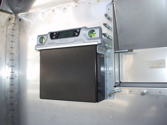
[Some of this entry is quite old] Finished fitting the battery box,
installing its three nutplates, and cutting the eight lightening holes
shown in the plans. Cutting the lightening holes took a long
time and completely dulled down two hole saws. A punch would
likely have worked much better, but I didn't have one. Anyhow, I
cleaned up the lightening hole edges, removed a bit of rust from the
inside surfaces of the box, and gave the entire box a coat of AKZO
epoxy primer. The battery box came powder coated from Van's,
but: 1. The lightening hole cuts need to be coated for corrosion
protection, and 2. As shipped from Van's, the inside surfaces of the
battery box didn't have good powder coat coverage and were already
starting to rust. Now with a coat of AKZO it should last a good
long time. |
| 2011.03.07: (0.0)
Fitted the various main DC power distribution components that will
mount on the forward side of the firewall.
Main battery
The main battery is an Odyssey
PC680, and the battery box has been fitted at the standard location as
described above.
Master and starter contactors
The master and starter contactors (Cole
Hersee p/n 24115 and 24021 respectively, Van's p/n ES 24115 and ES
24021) have been fitted at the standard locations. Although, I
made the firewall doubler a little bigger than Van's drawings to span
all the way between the two angle stiffeners (trying to minimize
firewall drumming).
Ground power connector and contactor
Fitted the ground power connector and contactor, which is my own
customization, not found in Van's stock design. See details here.
Main alternator and main buss fuses
Breaking from Van's tradition here, going in a different direction
inspired by the AeroElectric Connection.
Tradition is to run the main feed (master contactor output) and the
alternator B-lead into the cockpit to meet at the breaker panel.
The two big disadvantages of this approach are 1) bringing all that
alternator noise into the cockpit, and 2) risk of unstoppable
in-cockpit electrical fire in case of hard short in the alternator
B-lead or main feed wire forward of the breaker panel.
The alternate approach I'm taking in order to eliminate these problems
is to keep the alternator B-lead entirely on the forward side of the
firewall, and provide circuit protection against hard shorts for the
alternator B-lead as well as for the main feed to the cockpit via ANL
fuses on the forward side of the firewall. The obvious
disadvantage of this alternate approach is that if a fuse does blow,
it is not resettable/replaceable in-flight. But the
characteristics of ANL fuses are such that a "nuisance trip"
is virtually impossible (unlike typical alternator B-lead circuit
breakers). And furthermore, in the event that a hard short does
occur, there is little or no value to being able to reset or replace
the circuit protection device in-flight. The advisable course of
action would be to make use of the aux electrical system to safely get
on the ground, and only then troubleshoot the fault in the comfort and
safety of a hangar.
So... I mounted the two ANL fuse blocks (Bussman p/n 4164, sold by
B&C as p/n C903-1) below the master contactor, to minimize the
length of the unprotected main feed wire between the master contactor
and the ANL fuses. Note that these fuse blocks each mount with a
pair of 3/16" countersunk screws (not provided), and the
countersink angle in the fuseblock is 83 degrees, which is standard in
commercial hardware, not the 100 deg countersink angle that's standard
in aircraft hardware. I used 1 inch spacing (center-to-center
pitch) betweent he two fuse blocks.
The fuses themselves are 60A rated (Bussman p/n ANL-60, sold by
B&C as p/n C905), but it's important to note the actual
characteristics, shown in the Bussman datasheet as a time-current
curve. The ANL-60 will actually sustain upwards of 100A
indefinitely, somewhere around 200A for one second, about 600A for a
tenth of a second, and are ultimately rated to safely interrupt up to
2,700A, which is more than even a dead short across the battery can
produce. Bottom line is that these fuses will only ever blow
under a hard short, which is the one and only time we want them to
blow.
Note also that these are sometimes referred to as "current
limiters", which to me (coming from the electronics world) means
something very different. As far as I'm concerned, calling an
ANL a "current limiter" is misleading. It's a
fuse. Simple as that.
Main alternator B-lead shunt
Main alternator current will be measured using an 100A, 100mV
shunt. Mine comes from Advanced Flight Systems (p/n 44105) as
part of the engine sensor package, and is actually a DELTEC
MKA-100-100. But note that this is
actually a standard milspec part, and is available from a variety of
manufacturers and distributors. These shunts go back many
decades, and are known under several generations of specs and
designations, including (in chronological order, I think...) AN3900,
MS91586, type designation MSA800, and finally AA55524/1.
Firewall ground bolt
I'm deviating significantly from Van's grounding scheme. Van's
uses airframe grounding for airframe loads throughout, which is not
entirely unreasonable for a metal airplane (although it does have some
disadvantages, and my plan is to run dedicated ground wires).
But furthermore, Van's even uses airframe structure to conduct starter
current, by virtue of tying the battery ground wire to a bolt on the
firewall and tying the engine case ground wire to a different bolt
elsewhere on the firewall. I don't like that at all, for several
reason related to grounding reliability in general, starter
performance, and just the idea of running 200 amperes through thin
aluminum and stainless steel structure and how it may heat certain
parts of that structure or promote long term corrosion.
My plan is to run the three ground wires that carry starer current
(engine case, battery, and external power connector) to a single bolt
on the firewall. This will provide a lower resistance path for
starter current, and avoid running it through airframe structure
entirely. I will also run a fourth wire from that bolt to a
ground disribution point in the cockpit, from which ground wires will
fan out to the various airframe loads along with their (positive)
power wires. So the airframe is still grounded via the firewall
bolt, but is not generally relied upon nor used as a return path for
any significant loads (a few sensors and low-power loads still do get
ground via their case mounting, unfortunately).
Note that the AeroElectric Connection also promotes a central ground
point architecture using a "forest of tabs" component sold
by B&C, which is a brass plate with a bunch of fast-on tabs
soldered to it, and a 5/16 brass bolt and hardware for the heavy
ground wires. Not a bad idea, although I bought one of these
parts and was not terribly impressed with its quality, and had some
misgivings about structurally how it mounts. And anyway, I'm
planning on a PCB main box that will distribute most of the accessory
grounds along with their power, so the "forest of tabs"
aspect is redundant. So bottom line, I agree with the central
ground point philosophy they advocate, just wasn't crazy about how
these guys implemented it, so I'm rolling my own.
Note also that unlike AeroElectric/B&C, I'm not using any brass
hardware for my firewall ground point. Brass is often used in
this type of application as a compromise of physical properties,
primarily between conductivity (not nearly as good as copper, not
nearly as bad as steel) and structural strength (not nearly as good as
steel, not nearly as bad as copper). I'm using a standard AN4
bolt (cad-plated steel), which is very strong, and which in my
grounding architecture is not called upon to carry current and
therefore is not required to be a good conductor.
My firewall ground bolt (and nutplate on the aft side of the firewall)
is located toward the top of the diagonal stiffener, a point that is
both structurally solid and conveniently located for running the
ground wires that converge there.
Welding cable
Starter current can be as high as 185A (SkyTec 149-NL spec).
This of course is only for a few seconds at a time, so some overload
of wire specs by design is acceptable. Long story short, 2 or 4
AWG wire is generally used for all wires that carry starter
current. As for wires carrying alternator current, 60A
continuous puts us at 6 AWG.
Now, throughout the airframe I use almost exclusively milspec
tefzel-insulated wire for its proven physical properties, especially
as they pertain to abrasion and fire. But one undesirable
property of this milspec wire is that it is very stiff. Not a
problem for smaller wires. But in the heavy gauges of the
primary power distribution wires as discussed above, the stiffness
becomes a real issue, as the wire can exert significant forces on the
components that it attaches to. And the problem is even further
exacerbated where one end of the wire is subject to engine vibration,
as is the case with the starter, alternator B-lead, and engine case
ground wire. Terminals breaking over time is a common problem in
the field. And a proven remedy is to replace the stiff milspec
wire with welding cable, which is specifically designed to be very
flexible while still environmentally rugged. I'm going this way
from the start.
Now unlike standardized milspec wire, welding cable is a class of
commercial products that vary in physical properties from one product
to the next. So I did a little research to find the most
suitable variety. The type I settled on is called "Super
Vu-Tron Welding Cable", made by General
Cable under the Carol Brand. Compared to more typical
welding cable (such as General Cable's "Carolprene Welding
Cable"), Super Vu-Tron is even more flexible, uses finer strands
(34 AWG rather than 30 AWG), has a higher continuous current rating
for a given gauge, and uses an insulation material that is more
resistant to oils, solvents, and ozone.
I'm using Super Vu-Tron 4 AWG for wires carrying starter current, and
6 AWG for alternator current. [Note that I also bought a short
length of 2 AWG just to check it out. Still quite flexible, and
I think I could comfortably switch to it in the future if I find the 4
AWG insufficient. With 2 AWG it would mainly be just a weight
penalty.]
For termination I'm using AMP uninsulated brazed-seam ring terminals
(available from SteinAir and B&C, SteinAir being far less
expensive). Note that I've found that the best size match is to
actually use a terminal designated 2 gauge sizes smaller than the
cable, i.e. a 6 AWG terminal for 4 AWG cable, 8 AWG terminal for 6 AWG
cable.
I'm crimping the terminals onto the cable using a hydraulic crimping
tool from Harbor Freight (p/n 66150). Here too, the best match
between terminal size and tool die size is found by trial and
error. I've found that the 0 AWG die works well on the 6 AWG
terminal, and 2 AWG die works well on the 8 AWG terminal. Go
figure.
I'm putting 1 inch of heat shrink tube over each terminal end, black
on ground wires and red on (+) power wires. 1/2 inch shrink tube
fits well over 4 AWG wire, and 3/8 inch shrink tube over 6 AWG wire.
"Hot" terminals will also get an MS25171 rubber boot to
prevent accidental shorting by dropping a wrench, etc. Size
MS25171-3S over a 4 AWG wire, and -2S over a 6 AWG wire.
Copper bar
1/2 inch x 1/16 inch copper bar is used for short interconnects
between the contactor relays, and also between the two fuse blocks.
Note that the cross section of this bar is therefore 1/32 inch
squared, or about 40,000 circular mils, making it approximately
equivalent to (just slightly less than) 4 AWG wire. Van's
drawing shows two of these bars stacked in parallel connecting the
starter contactor to the master contactor, but I'm going with just
one, as the greater resistance over this short length should be
insignificant. And if I did find that more was needed, I'd use a
single 1/8" thick copper bar rather than stacking to 1/16"
bars, which can trap moisture and promote corrosion.
Note that I had to slightly modify the distance between the holes in
the copper bar to match the actual measured disance between the lugs
on the contactor relays. I also found that the lugs on the
continuous duty relays (Cole Hersee 24115) the
lugs are slightly angled down, which necessitated a slight bend in the
copper bars to get them to sit flat against the nuts. This was
true of both 24115 contactors (master and ground power), so I guess
it's not a defects... they just come this way?...
To protect against accidental shorting, I also put some shrink tube around
the exposed sections of copper bar to provide insulation. |
|
|