|
  

Canopy Frame and Plexiglass (Acrylic)
Running Total Hours:
0.0
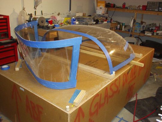
 | 2008.06.26:
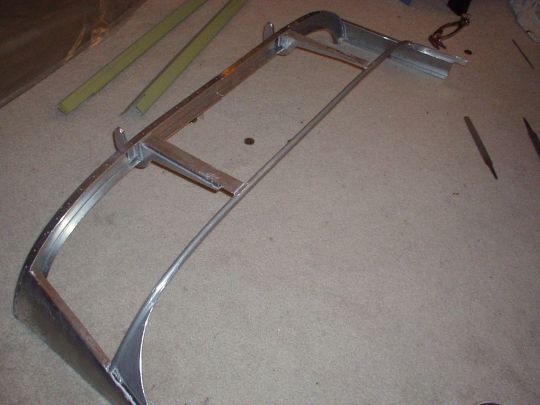
(0.0) The canopy
frame starts with WD-716A, a fairly complicated aluminum assembly that
comes welded from Van's. Nice idea, but nothing fits. Not
sure how they jig these for welding, but there's significant twist and
mis-shapen bends in the individual pieces, innacuracies in the
relative positions of the individual pieces, pre-punched holes in
individual pieces that are therefore misaligned relative to others,
you name it. This assembly needs to mate with the C-702 skin as
well as other components, and ultimately match the contours of the
fuselage very closely at the front and sides to form a smooth
continuation of those surfaces. I've been working with this
thing for over a week now, using every trick in the arsenal to
persuade it to fit. Getting closer, but man, what a pain in the
ass! I've heard other builders complain about this, and now I
understand.
 |
| 2008.07.29:
(0.0) Progress
report: Still working with this damn thing, but getting closer.
The WD-716A is now primed and riveted with the center splice plate,
and also the hinge pieces are riveted to the forward channels (with
various shims inbetween to set the right distance to the aft
tube). I'm still fine-tuning the fit of the canopy frame skin to
the forward fuselage skin by filing the WD-716A and adding shims as
needed. It's close enough now that I went ahead and drilled the
hinges. As others have experienced, the holes didn't end up
quite centered on the hinge material. So for edge distance
considerations, I decided not to use the big brass bushing inserts
from Van's, and make my own thinner ones. Whereas Van's bushings
are 3/8" outer diameter, I made mine from thin walled brass tube
with 9/32" outer diameter. That way I only had to enlarge
the holes in the frame to 9/32" (actually, I used a slightly
smaller "K" drill bit), thereby maintaining comfortable edge
distance. I easily press fit the bushings using the hand
squeezer.
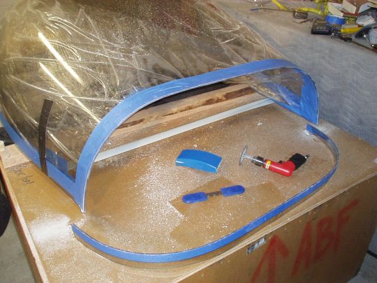
To break up the monotony, I also started working on the stiffeners for
this assembly. I think this was an afterthought by Van's, first
sold as an extra sub-kit, and now part of the main kit. Anyway,
these three pieces form a truss between the bottom flanges of the
WD-716A and the skin, which should indeed stiffen up this floppy
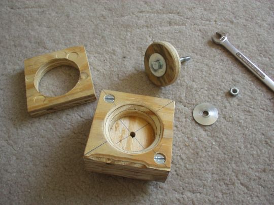
structure considerably. The stiffeners have a total of nine
2" diameter lightening holes already cut in them, but the builder
(me) has to bend a flange along the outline of the hole for
stiffness. Van's suggests going progressively around the hole
with a bending tool, but I doubt one could get nice results that
way. I decided to make what effectively amounts to a really big
dimple dye. I made it out of 3/4" plywood, and with a
1/4" bolt in the center to provide the pressure. A picture
is worth 1000 words, so without further ado:
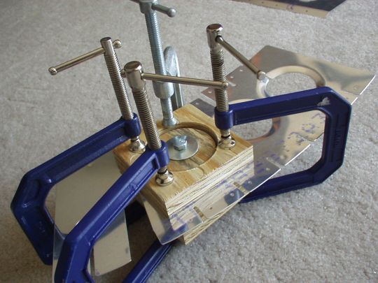
I was reasonably happy with the result. The flanges looked
more-or-less uniform, and they actually did stiffen up the part
considerably. For the outboard parts, the lighening holes also
had a groove on one end. For them, this "dimpling"
operation also put a little bit of curvature into the part in the
direction that it will need to curve to conform to the WD-716A.
Cool! |
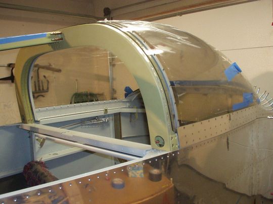
| 2008.08.19:
(0.0) Progress
report: Still working with this damn thing, but getting closer.
The forward canopy frame weldment and skin are coming together nicely,
and now fit the coutours of the fuselage pretty well. It took
five rather complicated shims, and a fair amount of filing on the
weldment's flanges. The first shim is along the forward top
rivet line. It is 0.062" thick in the center, and tapers
down and bends down on the outboard ends (2 rivets outboard of the
hinges). The outboard sections of the forward rivet line are the
opposite, where material had to be removed from the weldment's flanges
so that the canopy skin will not sit higher than the forward fuselage
skin (the infamous 2 and 10 o'clock "air scoops").
There are also shims along the upper of the two longitudinal rivet
lines on each side. Rather than force the skin to pull in to the
weldment, I decided to measure the gaps through the rivet holes, and
make shims to fit. This allows the skin to follow a more natural
curvature, giving a nicer appearance and also providing better overall
stiffnes to the structure. These shims vary in thickness along
their length, and also have some twist, most noticabley at the aft
end. The are also shims along the two longitudinal rivet lines
at the top (the weldment's members that run back from the hinge
arms). These compensate for the added height due to the first
(forward) shim, and also some undesired curvature that these weldment
members took on as a result of welding. In any event, the
varying thicknesses of these shims along their lengths were also
determined by measuring depth through the rivet holes in the skin.
Now with the aft canopy decks installed again in the fuselage, I'm
starting to fit the canopy frame sides. The bottom flanges on
these parts have already been shrunk by Van's to provide some of the
necessary curvature to match the fuselage sides, but not quite
enough. I'm trying to get a hold of a shrinker to complete the
job. Hoping to find one I can borrow, and not have to buy one
just for this one job... |
| 2008.09.23:
(0.0) Progress
report: I borrowed a shrinker from Gene and it made quick work of the
side rails. Got them fitted and riveted to the forward frame
weldment.
Fitted the stiffeners to the frame. This also required some
complex shims for a good fit. I added one shim between the
center stiffener and the skin, which tapers down at the outboard ends
to match fit the flat stiffener to the curved skin. I also added
shims to fill the gaps between the weldment and the skin where the
outboard 3 rivet holes are located by the stiffeners.
Fabricated and fitted the mounting blocks for the canopy strut
attachement on the frame side. See section Canopy
Support Struts.
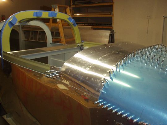
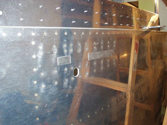
The outboard 3 rivet locations (both sides) between the skin and the
aft tube of the weldment have considerable gaps. The most
outboard rivet has a gap of approximately 0.300", the next one
approximately 0.250", and the next approximately
0.030". Furthermore, the gaps are significantly tapered, so
even a simple spacer wouldn't be a very good solution. I decided
to shim the 0.030" gap and build a little pedastal for the
0.250" gap. The outboard most location (0.300" gap) is
not conducive to any good solution I could think of, so I'll just
leave that one alone and put a dummy rivet in the prepunched hole.
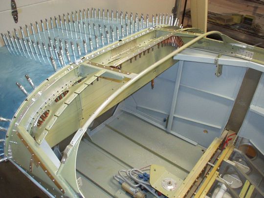
(photo was taken at a later date, but shows the
various shims discussed here)
WIth all this stuff fitted, I'm contemplating the next step.
Van's would have you start fitting the plexi now, with the frame still
held together with clecos. But I'm thinking that it would be
better to rivet the frame together now so it's stiff while fitting the
plexi, and also to reduce the risk of scratching the plexi with a
cleco. This does present a couple of chicken and egg problems
having to do with the "ears" in the skin and the
"tabs" between the forward weldment and the sides. A
search on "canopy, ears" on the forum yields much
discussion... I'm currently thinking that I will remove then
ears completely, partly because they are problematic in terms of fit
and fastening, but also this will eliminate the chicken and egg
problems with riveting the skin now. With the ears eliminated,
there is adequate access to the tabs, so they can be adjusted and
rivet at a later time even with the skin already riveted on. |
| 2008.10.04:
(0.0) Progress
report: I decided after all to proceed as instructed and at least do
the initial trimming of the canopy before riveting the frame. So
the frame is still held together with clecos, for now.
Before even doing any trimming on the plexi bubble, the builder's
manual says to mark a centerline on it. Sounds simple,
but... I found that it's not quite symmetric, and there are no
good reference points. Neither the clamp marks around the edges,
nor the extra material outside the clamp marks, are uniform.
Knowing that none of these are perfect references, I located a series
of center points based on each set of possible references, which
varied by as much as a half inch. I used a taught string from
front to back to make the line more or less straight, and ran it down
the "average" (eyeballed) of the center points I
marked. As best as I can tell, the accuracy of this centerline
isn't actually important. The only way I see it being used in
the manual is to keep the forward and aft canopy pieces in proper
alignment after they've been separated. I suppose this marked
centerline could also help in aligning the canopy on the fuse, but
really I think that fit rather than this sloppily marked centerline
will be determine final alignment.
On to cutting. The manual instructs to initially just cut off
the clamp areas on the sides and aft, and the extra flange in the
front. Sounds reasonable, but again there are no really good
references, so it takes some good eyeball work. Not knowing how
much extra material there is in the molded canopy, I was a little
nervous about cutting off too much. [But fast forward a couple
of days, all turned out well.] I did the sides first, making the
cuts about 1/4" in from the clamp marks, where the plexi is again
"clean" -- free of distortions and texture. I then did
the back, same idea. Lastly I did the front, which is
different. As it comes from the mold, the front of the canopy
has a substantial "flange" area, which actually closely
mimics the shape of the forward canopy frame skin. The
transition between this flange and the usable part of the canopy is
well defined around the center with about a 1/2" radius bend,
gradually becoming smoother and less defined outboard. I made my
cut such as to completely eliminate the transition area, which was
very clear in the center, and again used some artistic eyeball to
conservatively extend the curved cut outboard, where the transition
was no longer distinct.
Various tools and techniques for cutting and dressing the plexi have
been widely discussed on the forums. I also paid a visit to Ridout
Plastics, a local plastics shop (with online store as well), to
buy some tools and ask for any advice they might have to offer.
On the advice side, they were definitely very knowledgeable about
working with acrylic (a.k.a. "plexi"), and were happy to
chat about it. Their advice about cleaning up edges after
cutting was similar to that used by many builders -- a scraper tool,
and sand paper. On the cut itself, they suggested a hand-held
jig saw. To me that seems like asking for trouble because of the
reciprocating action and lack of support to the oddly shaped
canopy. I decided to first try Van's tried and true method using
a cutting disc in a die grinder. In any case, I also picked up
some scrap pieces of acrylic at Ridout so I could experiment and
practice on before doing the real thing. The die grinder worked
ok, but not great. Its low torque would tend to get it stuck,
and also necessitated running it at higher RPMs than I would like,
making it hard to control. Using Van's cutting disc in the
pneumatic drill worked out much better. Its high low end torque
made for much better controllability, especially for the first
pass. To summarize, either the die grinder or the drill can do
the job, but the drill is more controllable and ultimately leaves a
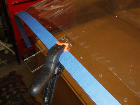
cleaner cut. BTW, whether I used the die grinder or the drill, I
didn't make the cut in one pass. I took about 5 or 6 passes to
cut all the way through the material. My technique was to first
mark the cut line by putting down blue masking tape. I put 3
layers of masking tape to give it enough thickness that it would
actually guide the tool back somewhat if I strayed too close to the
line. I then did a very slow and careful initial pass, using low
RPMs, to cut a shallow groove that will henceforth be the guide.
I then made additional passes with increasing RPM and pressure to
progressively deepen the groove, until the final pass cutting all the
way through. After the cut is made, the edge has to be smoothed
out. I found that the best way to do it is with a sanding
block. First with 60 or 80 grit, moving to 150 grit, and finally
400 grit. Then, chamfer the corners with the scraper tool.
Note that the side of the scraper tool without the grooves can also be
used to work down the edge, but I found that sandpaper works
better. The cutting operation can leave little burrs, and the
scraper would have a tendency to catch on these, whereas sand paper
does not. Note that all work on acrylic should be done at warm
temperatures (75° to 80° F is good). We've had some hot days
recently, which worked out perfectly. And otherwise I use a
1500W space heater to warm up the garage when necessary.
So after the initial trim, today I laid the plexi on the airplane for
the first time. Looks cool! To my surprise, it actually
fits pretty well (that's a first with anything related to the
canopy). Around the front there are some gaps of no more than
about 1/8" where it doesn't fit the contour of the canopy frame
quite right, but that should be easily fixed with another couple of
minor trims to the bubble. Above the roll bar there's only about
a 1/4" gap, which is better than most from what I've heard.
At the aft end there's about 2" of extra material, and about
0.5" along the sides. So I have to say, so far so good.
 |
| 2008.10.17:
(0.0) Progress
report: Several rounds of incremental trimming around the front of the
canopy, and it is now fitting the contour of the skin reasonably
well. It's not perfect yet, but I it will also change somewhat
after the big cut, with the canopy acutally resting on the cabin
frame, and also with the sides pulled in all the way to the side
rails, so good enough for now.
 |
| 2008.10.19:
(0.0) Progress
report: I made "the big cut", splitting the canopy into two
at the center of the cabin frame. It was a delicate job, but by
taking it slow and careful (over an hour just to cut an initial
groove), the results were about as good as one could hope for.
Nice clean straight perpendicular cuts with no major material removal
required to finish the edge. A couple of hours of sanding later,
and this milestone is now behind me. Now, to continue fitting
the forward canopy...
 |
| 2008.12.02:
(0.0) Progress
report: I was away on vacation for 3 weeks, but still since the last
log entry there's plenty to report. Progress is being made on
several fronts.
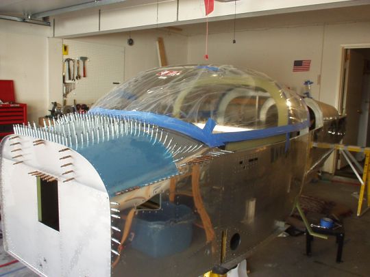
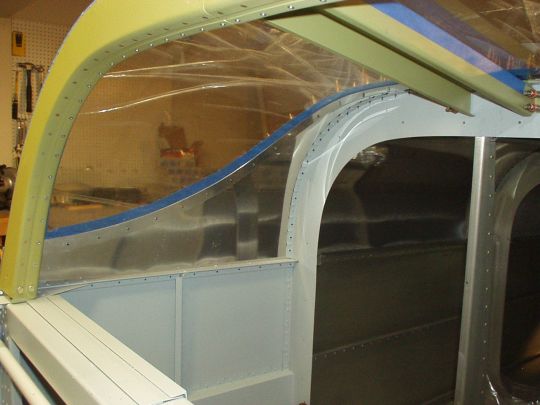
"Tabs": I've finished trimming the bottom (i.e. front and sides) of the
forward half of the canopy, and have adjusted and riveted the
"tabs" which connect the forward frame to the side
rails. This was a very iterative process, and the results are
not perfect but pretty good. The fit in the area with the
"tabs" and the "ears" still leaves some to be
desired, but at this point, the tabs and the frame's inner structure
are no longer the limiting factor. It's the contour of the
canopy vs. the contour of the outer skin of the canopy frame around
the "ears" is now the issue. It's not the ears
themselves that are the problem, but rather the fact the the
glareshield skin just forward of the ears does not provide any room
for the canopy bubble to transition through. A bit hard to
describe, but I'll add a picture that should clarify the
situation. Back to the problem, I could see two possible
solutions: 1) notch out more of the glareshield skin forward of the
ears, as some builders have done, or 2) bend a notch into the skin
without removing any material. It seemed to me that enlarging
the notch forward would significantly weaken the structure, or at
least make it lose some rigidity, so I opted for option 2. I
used a 1/4" steel rod to push in the skin and create a channel
for the bottom of the canopy to ride in. Again, this took some
trial and error, but ultimately the results were satisfactory.
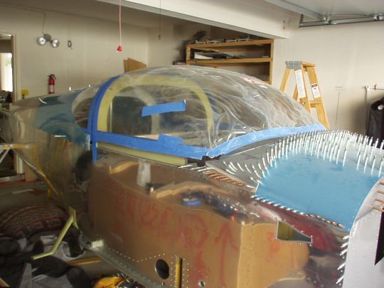
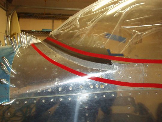
"Ears": I've also been deferring the decision on what to do
with the "ears", and now as I'm getting ready to rivet the
canopy frame skin on, it's decision time. The goals are to
ensure that the canopy glass is robustly held in position (it wants to
bow out), and to achieve a nice fit and finish. The deficiencies
in Van's design are that the ears don't naturally conform very well to
the canopy bubble, and that there are no fasteners or any other means
to secure the ears to the canopy glass. Forward of the ears a
fiberglass fairing will be formed in place, which will also blend over
the ears, but I want to make sure that the fiberglass and the aluminum
ears work together and not against each other... Again, hard to
describe, a picture should help. Anyway, my solution was to add
a screw through the aft end of the ear, sandwiching the canopy glass
between the ear and the frame just like along the side rails. So
this secures the aft end of the ear. And then forward of that, I
trimmed the ear down to about only 1/4" above the bottom of the
canopy. This will provide support for the canopy glass and keep
it from bowing out, but will ultimately be fully covered by
fiberglass. Since the forward part of the ear is cut that low,
the fiberglass fairing will be extended back over this area, and will
reach higher up than the aluminum on the canopy bubble, with the
fiberglass forming the final lines.
Lights: I decided to install an LED light strip under the glareshield
to provide panel lighting (and possibly cabin lighting, if I find it
sufficient). See Cockpit Lighting. |
| 2008.12.08:
(0.0) Progress
report: The canopy frame is primed, partially painted, and I've
riveted on the forward skin with Jimmy's help. So far its
holding its shape quite nicely. I've been doing everything as
much as possible with the canopy frame all clecoed together and
clamped down to the fuselage. I think that helped. I'm now
riveting on the stiffener kit. |
| 2008.12.11:
(0.0) Riveted the stiffeners to the
forward canopy frame. I was able to do the right side on my own,
with gun in right hand and bucking bar in left hand. But the
opposite feels too awkward, so Greg Larson came over and helped me do
the left side.
 |
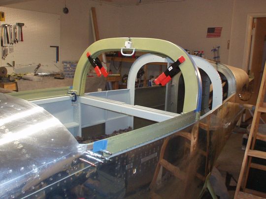
| 2008.12.15:
(0.0) Progress report: Final-fitted and
riveted the rear bow to the canopy frame.
Also, contrary to Van's recommended sequence, I went ahead and fitted
the side skins now, before the plexi is drilled. My reasoning is
that for drilling the plexi, the side skins can be clecoed in place to
provide the ideal "clamp" for holding the plexi in place,
and also serving as a drill guide. There is, as Van's notes,
quite a bit of flex in the side rails, so they will probably move
around some when pulled tight to the plexi. But that's an even
better reason to use them to hold everything in its final position
when drilling the plexi. And worst case if it does significantly
change the fit of the side skins, I can then always fabricate a new
set if necessary.
 |
| 2008.12.18:
(0.0) With everything clamped in place,
I marked the hole pattern for the rear canopy along the rollbar, and
the hole pattern for the forward canopy along the aft bow of the
canopy frame. I ended up using approximatly 2.25" spacing
(Van's recommends 2.5") to avoid edge distance problems with the
rivets in the canopy frame. I also started experimenting with
drilling on some scrap pieces of plexi. Doesn't seem too
bad. So I'm just about ready to start drilling the real thing,
but I have a temperature problem. Yes, it gets cold in winter
even in San Diego. Yes, cold is relative, but this 60° F
weather we've been having is too cold for my liking, and too cold for
safely working with plexi. I'd feel safer with 75° F.
Well, I ran my little 1500 W space heater for over an hour, and it
only got the garage up to about 65° F. I'll have to find a
heater with a little more UMPH! I don't think I want to wait
until summer to drill the canopy. |
| 2009.01.05:
(0.0) Progress report:
The weather isn't getting warmer any time soon, and I'm just not that
patient, so I went out and bought a second 1500 W heater. With a
total of 3 KW going, I was able to heat the garage to 75° F, and hold
it pretty accurately with the thermostats. I'm not looking
forward to the electric bill, but oh well. To keep things
precise, I'll will try to do all the plexi final fitting and drilling
as close as possible to 75° F.
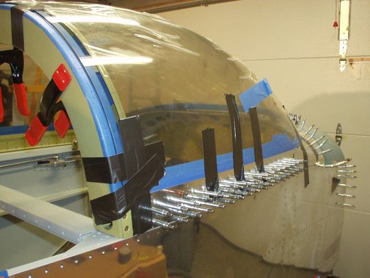
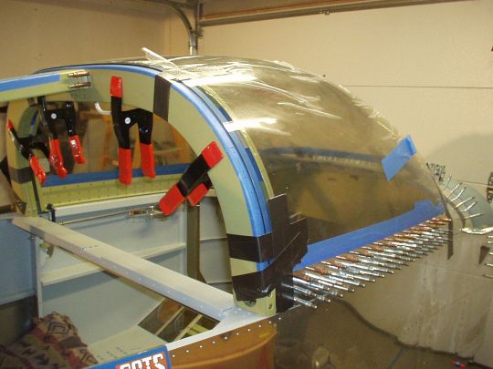
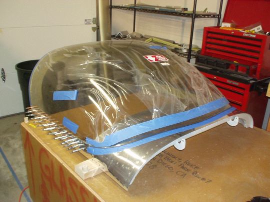
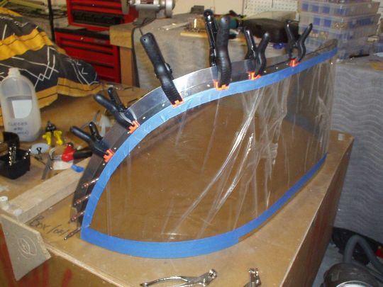
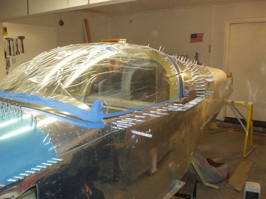
On to the drilling. I clamped the canopy frame to the fuselage
and positioned the plexi on it. I clecoed on the canopy frame
side skins, which nicely sandwiched the sides of the plexi in
place. I used duct tape to pull the plexi down into position all
around the sides, front, and back.
I then match-drilled the sides using the holes in the side skins as a
guide. Note that I did this using a 1/8" plexi drill bit,
even though I was drilling through a sandwich of aluminum - plexi -
aluminum. Since both pieces of aluminum were already pilot
drilled to 3/32", the plexi bit only had to enlarge those holes
to 1/8", which it did without too much difficulty. After
drilling each hole to 1/8", I then also ran a #30 reamer through
it, which produced immaculately clean holes, and also prepared the
canopy to eventually be countersunk using a bit with a #30
pilot. (I also deburred the holes using a permagrit countersink
bit once the plexi was removed from the frame.)
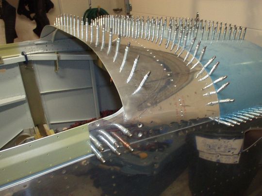
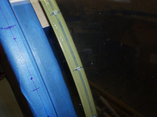
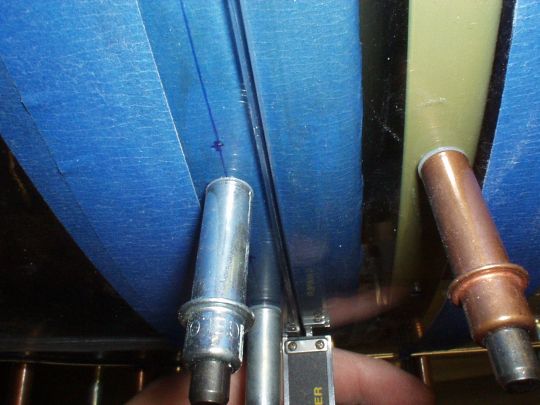
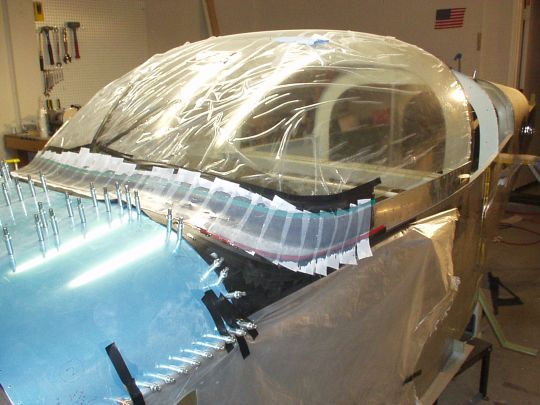
With the sides drilled and clecoed, I moved on to the aft edge (i.e.
the arch that matches the rollbar). These, I did not drill in
place. I transferred the hole pattern that I marked on the
canopy frame arch onto the canopy, just in sharpie on the protective
plastic, so that I could double check the straightness and evenness of
the hole pattern. I then only pilot drilled less than half way
through the plexi, just to set the hole locations. [Note: In the
photo it looks like the holes are messy with big burrs, but that's
just the protective plastic. The holes in the plexi are actually
very clean with no discernable burr.]
I then removed the plexi and drilled the holes through it on the bench
(1/8" plexi drill bit, #30 reamer, permagrit countersink for
deburr). When drilling the plexi I clamped another piece of
scrap plexi with matching curvature to the inside as backing material,
to prevent the bit from punching through or chipping the back of the
hole.
I then put the plexi back in position on the canopy frame, of course
clecoing all around the sides, and match-drilled the aft arch using
the holes I just drilled in the plexi as guides. I drilled the
frame using a standard (i.e. non-plexi) 1/8" drill bit, and then
ran the #30 reamer through the plexi and frame again. Great
results.
I have only two more holes to drill through the plexi of the forward
canopy (there's always something...). Recall that the
forward-most hole on each side is one that I added that goes through
the forward skin, not the side skins. And I had to already
enlarge and dimple the hole in the skin for the #6 screw before I
riveted on the skin. I wisely left the opposite hole through the
inner side rail at 3/32". But this does mean that I have to
match-drill this one from the inside rather than from the
outside. So I'll do this at the next convenient opportunity.
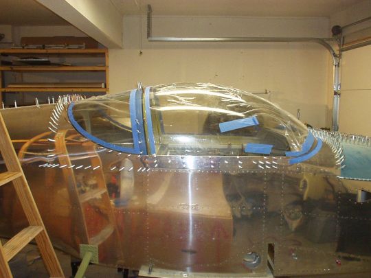
I also started fitting the rear window. I can see this is going
to be a real PITA, because the top of the rear window plexi is
substantially concave along the fore-aft axis (what Van's calls a
"duck tail"?), which causes it to press against the
structure between the roll bar at the front and the bulkhead at the
back. The plexi will be under stress, and will not interface
with the skin nicely in the same plane. Damn it... I
anticipate this being another one of these "massaging"
situations. In the mean time though, I prepared the top skin,
chamfered its edges, and marked and pilot-drilled a hole pattern for
the screws that will connect the plexi. I also took this
opportunity to correct the angles of the flanges in the bulkheads that
mate up with this skin. The QB factory over-bent these by a good
30 degrees. |
| 2009.01.14:
(0.0) Progress report:
Working on the rear window. Despite the concavity issue, the fit
has actually turned out pretty descent, with the plexi pulled down to
the roll bar with only a moderate amount of force -- not enough to
cause any problems.
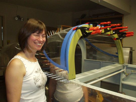
I drilled the rear window starting in the aft center, working outwards
left and right while the forward edge of the window is clamped down to
the roll bar, and Stacey pushing the window from the inside tightly
against the fuselage skin. About the photo: after 5 attempts I
gave up on getting a photo with her eyes open, oh well.
I then drilled the holes along the front edge of the rear window in a
similar fashion as I did the aft edge of the forward canopy. I
first transferred the hole locations to the plexi (covered with
transparent celotape) with sharpie pen, and then I drilled. But
unlike the aft edge of the forward canopy, this time I went ahead and
drilled the plexi while still in assembly on the fuselage, all the way
until the drill bit hit the roll bar. The holes in the roll bar
will ultimately be drilled and tapped for 6-32 screws, so that's a
smaller hole than 1/8". Letting the 1/8" plexi bit
just hit the roll bar will later help as a center guide for drilling
through the roll bar. I removed the plexi from the fuselage and
finished drilling the holes all the way through the plexi, and then
reaming them to #30. I then clecoed and clamped the rear window
back to the fuselage, and drilled through the roll bar to 1/16"
(which will serve as pilot holes for the #36 drill prior to
tapping). I chose to have the plexi on the fuselage for this
operation only in order to help drill the holes at the right angle,
perpendicular to the surface of the plexi, which is not exactly the
same as the roll bar. Anyway, it is also much easier to sight
the angle with the plexi in place, because I can clearly see the
reflection of the drill bit. Anyway, that's done. But then
I discovered that I don't have a #36 drill bit, so that'll have to
wait.
The forward edge of the rear window matches nicely to the roll bar
center line, with only a couple of high spots that still need a bit of
sanding. I marked these with masking tape and will take care of
them at the next convenient opportunity.
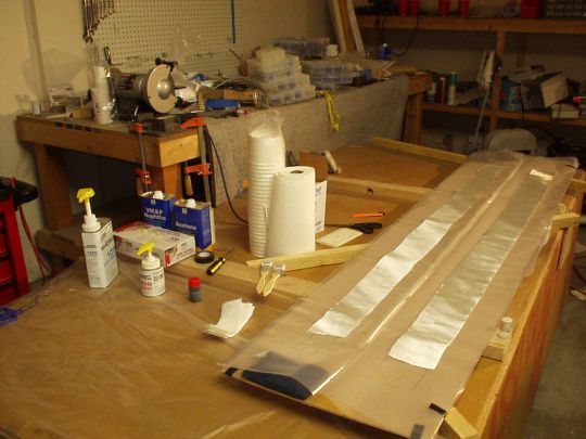
My next major task for the rear window will be to make the
"optional" backing strips shown on the plans. I think
this is a good idea, as it will help spread the load from the
fasteners more evenly across the edge of the plexi. It will also
make for a nicer looking finish on the inside.
Today I also drilled the two remaining holes through the forward
canopy. Just clecoed the plexi back to the frame, and drilled
through from the inside. I still need to trim the aft edge, and
will probably do so in the next few days. I also marked with
masking tape the line where the canopy meets the glare shield. I
plan to paint the glare shield (the portion inside the canopy) flat
black.
 |
| 2009.01.24:
(0.0) Progress report:
Fabricated 0.025" aluminum backing strips for the rear
window. Came out nice.
Did a couple of last iterations of final fitting (sanding only, no
cutting) to get the gap between the forward canopy and the rear window
to an even 1/32". Now with everything clecoed in place, the
canopy opens and closes with no interference. Looks sweet!
The fit between the forward canopy and the rear window is almost
perfect along the top of the roll bar, but not so great on the
sides. Basically, the rear window sticks out further than the
canopy, presenting a "step" to the airstream. A
careful examination of the airframe's geometry makes it clear why this
is the case. At the roll bar, the fuselage is tapering back,
becoming narrower as you go aft. The plexiglass canopy also has
a similar contour. The roll bar however is simply square, it
doesn't match this taper. As a result, the plexiglass and the
outside of the roll bar are not exactly in the same plane. Now,
the forward canopy has been fitted to mate neatly against the
centerline of the roll bar all the way around. So only the very
aft edge of the forward canopy plexi actually contacts the roll bar
near its centerline, and the plexi sits a little higher (i.e. not
making contact) at the very forward edge of the roll bar. In the case
of the rear window, the mismatch is in the opposite direction, such
that the window plexi only contacts the very aft edge of the roll bar,
and the very forward edge of the window sits a little bit higher (i.e.
not making contact) at the centerline of the roll bar. Hence the
mismatch at the roll bar centerline. Again, along the top this
is alost indiscernible. But on the sides the mismatch peaks at
about 0.040", quite noticeable to me and to the airstream
(drag!!!). We'll I've been debating anyway for some time whether
or not to make a targa strip. Now it looks like I pretty much
have to.
Started experimenting with various tools and techniques for
countersinking the plexi (using scrap for now). I haven't gotten
a result I've been really happy with yet, so this effort will
continue. |
| 2009.02.16:
(0.0) Progress report:
The plexi (canopy and rear window) is countersunk and drilled to final
size.
I experimented with several methods (on scrap) for countersinking
suggested by other builders, and some worked better than others.
First attempt: The permagrit countersink bit gave surprisingly rough
results. The grit was just too coarse. Second attempt: My
standard 3-flute machine countersink bit in a cage first gave mixed
results. It was difficult to start, required a scary amount of
pressure, and left a mostly smooth cut except for some subtle
rings. Third attempt: I had a hunch that the problems with the
3-flute cutter may simply have to do with it being well used and not
so sharp anymore. I bought a new cutter, which worked much
better. It took less pressure, although still quite a bit, but
cut consistently and left a totally smooth countersink. I did
the real thing using this technique.
After countersinking, I still had to enlarge the hole to its final
size. This was relatively easy, with several good options.
Just running a 5/32" plexi bit through it does the job pretty
well. Being extra cautious, I thought I would also follow that
up with a #22 reamer, to leave an even cleaner hole. That also
worked well. But it turned out that I could skip the 5/32"
drill, and use the #22 reamer directly on the existing #30
holes. That's how did it.
After doing this I did a final fit check, and ended up trimming just a
tad more from the left side bottom edge of the canopy to make sure it
doesn't interfere with the joggle in the side rail. Hopefully,
that's the last plexi trimming I will ever have to do! ;-)
With everything trimmed and fitted, it was time to button up the
canopy frame. I final drilled/reamed and countersunk the side
rails and skins, and riveted on the skins. Also made an external
lifting handle on the pilot side. Another fit check after
riveting and everything looked pretty good. I had to trim the
bottom edges of the side skins a touch more, and everything was
perfect again. And I was pleasantly surprised at how easy it was
to insert and remove the plexi despite the dimpled screw holes in the
side skins.
I decided to attach a pair of spacers below the aft ends of the canopy
side rails that would sit against the fuselage canopy deck when the
canopy is closed. That way, the vertical position of the canopy
is limited by the metal frame rather than the aft edge of the
plexi. I carefully adjusted the thickness of the spacers
(1/8" main spacer, plus thin adjustment shims), trimmed the
canopy latch cams ("fingers") a smidge, and in doing so got
the thing to sit solidly when closed, and let the latch handle operate
smoothly without excessive stress/strain during the over-center
transition.
Gave a coat of gray paint to the remaining interior surface of the
canopy frame, except for the top surface of the glare shield, which
will get a coat of black paint.
Another little refinement done on many tip-ups, I create a funnel-like
guide along the roll bar that lines up the canopy laterally as it
closes. The canopy structure is still pretty flexible, and this
mod helps prevent careless bumps and snags that could damage the
canopy if closed while out of alignment. Note that it is still
possible with extreme twisting of the canopy frame to miss the funnel
guide completely. And in any case, the canopy should always be
closed carefully and gently, so it doesn't just slam down. It is
not nearly as foolproof as, say, a car door. |
| 2009.02.22:
(0.0) Progress report:
I bought a "deluxe glare shield trim" piece from Classic
Aero Designs. This provides a padded covering for the glare
shield edge, which is a good safety feature. It also hangs down
about 3/8" below the glare shield edge, which will help hide the
light strip from direct line of sight. Hiding the light strip is
not for aesthetics, but rather to prevent looking directly at the
light source and ruining night vision. On aesthetics though,
this trim piece is nicely upholstered in a black synthetic leather and
looks very nice.
I fitted the trim piece to the glareshield, which merely involves
locating some screw holes. I then painted the top of the glare
shield flat black (Krylon Fusion 2519 Flat Black). And once that
dried, I installed the LED strip on the bottom of the glare shield. |
| 2009.02.25:
(0.0) A big day (or actually, a long
night). I attached the plexi bubble to the canopy frame for
good. Difficulty-wise, this would have been a non-event, except
that I decided to use fuel tank sealant (a.k.a. "pro-seal")
to seal the interface between the plexi and the side skins. That
stuff is a nasty, sticky, goopy, stinky compound with a limited
working time, and is very tenacious once cured. So I had one
chance to get it right. And I did. Whew.
Some other details to note. Rather than the nylock nuts called
out on the plans, I decided to use acorn nuts. This is motivated
by my goal to not have any sharp protrusions in the cockpit (the sharp
protrusions being the end of the screw coming through a nylock
nut). Since the acorn nuts don't have locking nylon inserts, I
used a dab of thread locking compound (Loctite ???). I did this
VERY CAREFULLY so it never comes in contact with the plexi. To
reduce glare I also painted the acorn nuts and washers with my
standard interior paint. I did this about a week prior to the
installation. With the hardware pre-painted before assembly, I
don't have to worry about painting anywhere near the plexi.
Man, it's nice to have this step behind me. I'll take a moment
to admire it before getting back to work :-).
 |
| 2009.03.06:
(0.0) Quick update: I'm getting ready
to do the composite fairing around the forward edge of thre
canopy. Before I do though, I'm going to get my hands dirty with
some less ambitious composite work on the wing tips and empennage
tips. Just to gain experience and confidence working with
composites, and lessen the probability of making a high-stakes mistake
on the canopy. Stay tuned. |
| 2009.03.09:
(0.0) Did a bit of composite work on
the wing tips, and that went pretty well. So back to the
canopy. I started by creating a structural (flox) fillet all the
way around the front, trying to basically continue the contour of the
outer surface of the plexi all the way down to the aluminum
skin. Came out pretty good. But I think I'll do one more
pass to fill in some low spots before doing the layups. My goal
here is for the layups to have a continuous surface with a uniform
contour to lay on. I don't expect this to be perfect and it will
not be the final finished surface. Non-structural fairing filler
(i.e. "micro") over the layups will serve that
purpose. But having the layups conforming to even gentle
contours should provide maximum strength, as well as a good foundation
for the subsequent fairing filler.
Note in the photo that the flox fillet is gray, not white. This
is due to black pigment that I added to the mix. I will do the
same with the layups. The idea is to keep the cockpit interior
color-neutral so it's not visually distracting, and to minimize glare.
Note also the red electrical tape in the photo. This masks off
my planned boundaries for the fiberglass fairing. The top
boundary is approx 5/8" from the edge of the plexi all the way
around, and approx 1" from the aluminum skin in the front and a
bit more around the sides due to the fillet angle. Van's drawing
shows 1" overlap of the plexi proper (i.e. excluding the fillet),
but I believe that 5/8" should be sufficient structurally in this
application. The reduced overlap makes the fairing match the
side skins better aesthetically, and also is less obtrusive to the
pilot's forward visibility from the cockpit. I have a STRONG
preference for cockpits that give a good high view over the
cowl. The RV-7A is actually not stellar in that regard, but I'll
do what I can to that end.
P.S. one more note about surface prep. 1. Clean with VM&P naphtha (what is "VM&P"???). This is one of the
few solvents that is reportedly safe to use on plexi. 2. Abrade
with red scotch brite pads. 3. Another pass with naphtha.
 |
| 2009.03.16:
(0.0) Did several more rounds of
fill & sand on the flox fillet, and it is finally a beautifully
contoured work of art! Around the front it's basically a
continuation of the plexi's contour, plus a radiused transition to the
aluminum. The areas around the sides were a bit more tricky,
where the continuation of the plexi's contour would actually end up
never intersecting the aluminum skin. So here I just used an
artistic eye to blend the contours. I also blended a bit of flox
around the aluminum "ears", so that the fiberglass will have
a continuous surface to conform to. |
| 2009.03.19:
(0.0) Laid up fiberglass around
the front of the canopy. Following the advice of Dan Horton
(composites guru on VAF forums), I ended up doing this using the
pre-preg sandwich method, three plies of RA7781 all at once, a
full-length strip reaching all the way around. John Nichols came
over to help me with this, which was a good thing. With the two
of us, this was a difficult, messy, aweful task. By myself this
would have been impossible. The results were decent.
Inevitable there are some small voids that need feeling, and lots of
blending (fill, sand, repeat) that I have to look forward to.
But that's how this goes.
I also added black pigment to the epoxy, which had mixed
results. I added enough to make the epoxy appear pitch black in
the mixing cup. But when I used it to saturate the cloth, it
became apparent that much more would have been needed to really do the
job. The wet cloth was a bit darker in appearance than normal,
but still quite transparent. Now that it's cured, it looks dark
gray from the outside, but not very dark at all from inside the
canopy. The fiberglass is still quite transparent when
back-lit. We'll see how it does once its exterior is primed and
painted. Anyway, however it is, I'll have to live with it at
this point.
As a side note, I am now soooooo happy that I built a (mostly) metal
airplane! I couldn't imagine doing nothing but this nasty
composites work for several years!
 |
| 2009.04.16:
(0.0) Sanding...
 |
|
|